Tape Path Roller Bearing Replacement.
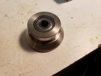
I replaced the ball bearings in the roller on the supply side and the impedance roller on the take up side.
Replacement was a snap. I elected to go with moderately priced Japanese made NTN brand 607Z bearings which are comparable to the original (and worn out) SKF bearings.
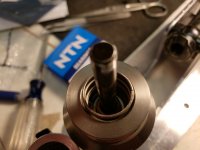
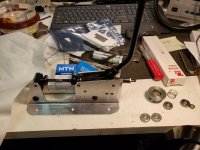
I used a roller skating bearing press to remove the old bearings. I removed the encoder assembly on the impedance roller before replacing the bearing.
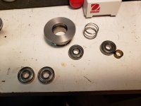
The puller is necessary to remove the old bearings and to press in the rear bearing which is a fairly tight fit. It bottoms against a C clip in the bore. In addition there is a spacer and spring that need to go back in before installing the top bearing.
The top bearing bore is slightly larger than the bottom and the bearing when pressed into place may exit enthusiastically due to spring pressure. The bearing can be secure with a tiny dab of high viscosity super glue if desired. Needless to say do not get it anywhere except for a spot on the outer race.
Runs much smoother, interestingly it sounds a bit cleaner on the top end which came as something of a surprise. The old bearings on the supply side were in rough shape and ran roughly even after lubrication.
I replaced the ball bearings in the roller on the supply side and the impedance roller on the take up side.
Replacement was a snap. I elected to go with moderately priced Japanese made NTN brand 607Z bearings which are comparable to the original (and worn out) SKF bearings.
I used a roller skating bearing press to remove the old bearings. I removed the encoder assembly on the impedance roller before replacing the bearing.
The puller is necessary to remove the old bearings and to press in the rear bearing which is a fairly tight fit. It bottoms against a C clip in the bore. In addition there is a spacer and spring that need to go back in before installing the top bearing.
The top bearing bore is slightly larger than the bottom and the bearing when pressed into place may exit enthusiastically due to spring pressure. The bearing can be secure with a tiny dab of high viscosity super glue if desired. Needless to say do not get it anywhere except for a spot on the outer race.
Runs much smoother, interestingly it sounds a bit cleaner on the top end which came as something of a surprise. The old bearings on the supply side were in rough shape and ran roughly even after lubrication.
Attachments


Hi Kevin,
-Chris
Well, not too surprising if you consider varying tape tension, and FM noise due to varying friction. That's one reason why the three head Nakamichi cassette decks sound so good. They push the pressure pad away from the tape and head. Those machines are pretty much the same as an open reel machine's tape path.interestingly it sounds a bit cleaner on the top end which came as something of a surprise.
-Chris
Just grabbed a pair of good reel table holders, will have to change the trident locks but I have a good pair.
Replacing Panel Trim on an MX5050
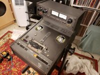
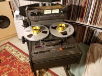
Much of the sheet metal on my MKIII-2 is in pretty rough shape, I've been replacing them with better bits as I can get my hands on them.
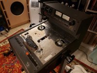
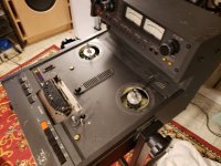
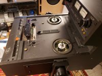
Today I replaced the transport sheet metal with a less than perfect, but nevertheless better bit of trim than was on the machine.
I encountered one problem removing the Athan sourced pinch roller and which I have not reinstalled. The bearings fit too tightly on the pinch roller shaft. I ruined neither bearings nor pinch roller, but I am going to see if I can get some bearings that fit better.
There are lots of trim bits to remove prior to removing the trim cover. Once removed there are two bits of double sided tape to be overcome carefully. Not much more to relate really, it's pretty quick.
I did finally score a decent head cover so that will go on next.
I will report on other modifications to this machine as they occur. (It is still the test mule and the one to beat.)
Much of the sheet metal on my MKIII-2 is in pretty rough shape, I've been replacing them with better bits as I can get my hands on them.
Today I replaced the transport sheet metal with a less than perfect, but nevertheless better bit of trim than was on the machine.
I encountered one problem removing the Athan sourced pinch roller and which I have not reinstalled. The bearings fit too tightly on the pinch roller shaft. I ruined neither bearings nor pinch roller, but I am going to see if I can get some bearings that fit better.
There are lots of trim bits to remove prior to removing the trim cover. Once removed there are two bits of double sided tape to be overcome carefully. Not much more to relate really, it's pretty quick.
I did finally score a decent head cover so that will go on next.
I will report on other modifications to this machine as they occur. (It is still the test mule and the one to beat.)
Attachments
-
 9 - done except head cover.jpg417.1 KB · Views: 120
 -
 8 - new_isher2.jpg411.6 KB · Views: 97
 -
 7 - gone.jpg349.8 KB · Views: 93
 -
 6 - ready.jpg314.3 KB · Views: 107
 -
 5 - switch trim panel.jpg298.9 KB · Views: 96
 -
 4 - tensioners off.jpg426.8 KB · Views: 103
 -
 3 - head cover off.jpg373.8 KB · Views: 94
 -
 2- tables off.jpg419.8 KB · Views: 122
 -
 1 - getting started.jpg439.4 KB · Views: 135
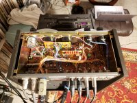
What are the trafos at the floor in the pics? Do you think on repaint the main table that appears age worn?
Congratulations, friend!
Congratulations, friend!
What are the trafos at the floor in the pics? Do you think on repaint the main table that appears age worn?
Congratulations, friend!
Off topic! LOL They're the power transformers for one of a pair of GM70 amps I am building for a friend. I'll send you some pictures once I get rolling.. 😀
I was thinking of repainting some parts of the deck, but getting colors to match is more work than I currently have enthusiasm for. I may replace the front panel corner piece, but that's about it. These machine is 31 years old and had a hard life, and was stored unceremoniously in an unheated garage for about 8 years - it's a wonder I got it running at all. Lots of small problems and many parts electrical, electronic and mechanical have been replaced.
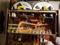
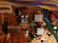
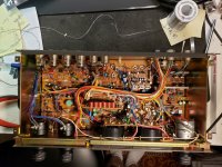
One bad thing I can attest to is that LME49860 produces a pretty significant output transient at power down that JRC4560s do not - consequently I will probably not use this part in the record path unless I can assure no DC pulse will get to the record head.
Just one of the sections now covered by LME49860 is after the mute circuitry, but that's all it took. The pulse approaches SRL on the output which means it is around 4 - 5Vpk! (There is gain after it) Not cool, it may magnetize the cores in my input transformers over time.
Just one of the sections now covered by LME49860 is after the mute circuitry, but that's all it took. The pulse approaches SRL on the output which means it is around 4 - 5Vpk! (There is gain after it) Not cool, it may magnetize the cores in my input transformers over time.
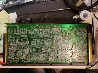
You need to make sure LME49860 is free of oscillations ... otherwise is hard to explain such behavior at a very first view.
Did you put bypass capacitors on the 49860's rails? Or, at least a 0.1µF cap between +V and -V.
Interestingly there are 11 pairs of 0.1uF bypass caps with a pair right near these op-amps. (I may add some more)
Scope shows no evidence of oscillation - I may need to dig out the 100MHz analog scope.
I did not look at the turn off behavior so I will need to revisit it. There may be a relatively simple fix or I may simply not care.
The biggest benefit comes from installing in the first stage which is muted. There was an incremental improvement in playback with the additional op-amps.
Hmmmm.... Rod Elliott also found this strange phenomena with TL072 chips in his crossover project, and put in a mute circuit to avoid it.......He said 4558s did NOT do this, but I'd hate to use those for anything!
These replaced 4560s. The other machine with stock op-amps does not do this and I am 99.99% sure this one didn't before I changed the op-amps.
The day I forget to mute the pre-amp could be the day that I fry my bass amps and woofers so I will either need to fix this eventually or undo this mod - a shame because it's definitely an audible improvement.
I will not be changing out any more in this machine since modern high voltage op-amps appear to be unsuitable for audio use unless you use a mute circuit.
I will verify that the supplies collapse in a symmetrical manner, other than that there isn't much I can do unless I add a muting circuit.
Man, that's a shame! Surely one of the geniuses here on the forum can come up with a solution. Bleeder resistors across the power supply caps? Lower the +/- V and use 4562s? Someone MUST have come across this before.I will not be changing out any more in this machine since modern high voltage op-amps appear to be unsuitable for audio use unless you use a mute circuit.
I can think of several solutions and may try a few when I have a bit more time.
The LME49860 is reputedly nothing more than the high voltage version of the LM4562 so I suspect swapping it in with a lower PSU voltage probably isn't going to fix it.
The LME49860 is reputedly nothing more than the high voltage version of the LM4562 so I suspect swapping it in with a lower PSU voltage probably isn't going to fix it.
Good point; but I have dozens of 4562s in my gear and have never encountered the problem you are describing. Hmmmm.... wonder if it is somehow power-supply related? Maybe you could shoe-horn in one of LV's NoNoiser circuits? D-Noizator: a magic active noise canceller to retrofit & upgrade any 317-based V.Reg.The LME49860 is reputedly nothing more than the high voltage version of the LM4562 so I suspect swapping it in with a lower PSU voltage probably isn't going to fix it.
It's definitely something I need to measure, the schematics indicate that the supplies are symmetrical or should be depending on the loading.
It's pretty much the op-amps.. LOL I installed some more tonight, and it got even worse. I will likely add muting relays at the output at some point.
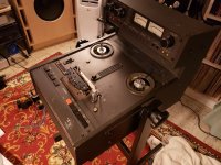
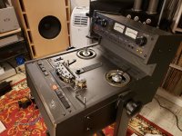
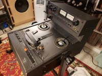
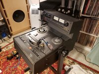
Apparently the better op-amps are audible, although given the whole record and playback process I sort of wonder why. I figured the process was so flawed that replacing a device orders of magnitude closer to mathematical perfection would be inaudible due to the gross errors elsewhere, this doesn't seem to be the case. I will admit I have made a lot of changes to this machine that contribute to the improved performance so at some point I need to measure a few things and see how good this machine is against the original performance claims.
I should probably take some more pictures of this machine, it looks a whole lot less shabby than when I got it. (Still some obvious signs of wear and tear but a lot of things have been replaced..
Attachments
-
 20190819_211553.jpg436.9 KB · Views: 122
 -
 20190819_210201.jpg272.8 KB · Views: 123
 -
 20190819_210148.jpg357.8 KB · Views: 174
 -
 20190819_210141.jpg364.1 KB · Views: 180
 -
 20190819_210128.jpg534.2 KB · Views: 178
 -
 20190819_210007.jpg626.2 KB · Views: 188
 -
 20190819_211524.jpg500.6 KB · Views: 192
 -
 20190819_220407.jpg492.6 KB · Views: 131

- Home
- Source & Line
- Analogue Source
- So you think you want to play with tape: An Otari Story