Hi Kevin,
Some of the Tascam machines managed a better top end, but that was in practice actually measuring the response. I think their specs were down at 22 K, we were able to hit 27 K, but that was at 15 ips.
Your s/n looks right. A Dolby SR module would take that spec much higher. Of course, the more effective the noise reduction system is, the more critical your calibration is too. Your Amber 3501A will give you measurements accurately. You really don't need much more than you have. If you put your RTX in frequency response mode (you can use ARTA), you will see how flat your response is. M.I. would tell you everything you want to know and more.
-Chris
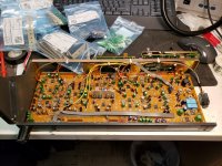
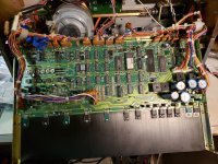
Some more progress to report on the MX-50N, today I replaced most of the electrolytic capacitors and modified the LF compensation circuit by replacing the pots with fixed resistors. Since I am not changing the heads on this machine this isn't a problem.
I have managed to keep the board clean as I do the reworks and determined that the SRL led that doesn't light is actually bad. I've ordered some replacement LEDs.
The sharp eyed will notice a trace or two that appear funky due to a discoloration of the solder mask - I initially thought these traces were open, but careful checking reveals they are in fact just fine.
Early next week I should have the remainder of the capacitors required and will re-install the audio module soon.
I will move on to cleaning the logic PCB and then replace all of the electrolytics on it as well.
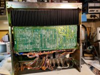
I have cleaned up the corroded components and used a rust inhibitor and painted them.
I actually will have a parts unit soon, so I may swap some parts.
In other news an MX-55 could be headed this way - no idea where I will store it until I can look at it. A friend has one that needs a new home, hoping it is an N and not a D version as the D is a huge bridge style recorder and I can't fit another one. (The MKIII-2 is enough)
I have managed to keep the board clean as I do the reworks and determined that the SRL led that doesn't light is actually bad. I've ordered some replacement LEDs.
The sharp eyed will notice a trace or two that appear funky due to a discoloration of the solder mask - I initially thought these traces were open, but careful checking reveals they are in fact just fine.
Early next week I should have the remainder of the capacitors required and will re-install the audio module soon.
I will move on to cleaning the logic PCB and then replace all of the electrolytics on it as well.
I have cleaned up the corroded components and used a rust inhibitor and painted them.
I actually will have a parts unit soon, so I may swap some parts.
In other news an MX-55 could be headed this way - no idea where I will store it until I can look at it. A friend has one that needs a new home, hoping it is an N and not a D version as the D is a huge bridge style recorder and I can't fit another one. (The MKIII-2 is enough)
Attachments
The damaged MX-50N is not going to be cosmetically restored although I will do my best to prevent any further corrosion damage, and some components if spares become available may be replaced.
I fail to see how replacing the LF EQ pots with fixed resistors is an improvement. What if you want to align your machine to play a tape recorded on another deck? What about drift? I don't think fixed vs. adjustable resistance offers any sonic advantage whatsoever--- Do you? I do think replacing the electrolytics is an excellent idea in a 40-yr. old machine; I should do the same to mine!!Some more progress to report on the MX-50N, today I replaced most of the electrolytic capacitors and modified the LF compensation circuit by replacing the pots with fixed resistors. Since I am not changing the heads on this machine this isn't a problem.
Good morning Kevin,
-Chris
That sounds perfectly reasonable. If it came to it, you could repair it cosmetically later on.The damaged MX-50N is not going to be cosmetically restored although I will do my best to prevent any further corrosion damage
Now that's cool. I would hope that it was the version with the meter bridge. Space can always be found for it. It looks like you're going to have to start collecting A-77 and B-77 units. Small and they have a handle. Personally, I would go for the B-77 every time (unless there was an A-700 being offered).In other news an MX-55 could be headed this way ...
-Chris
I fail to see how replacing the LF EQ pots with fixed resistors is an improvement. What if you want to align your machine to play a tape recorded on another deck? What about drift? I don't think fixed vs. adjustable resistance offers any sonic advantage whatsoever--- Do you? I do think replacing the electrolytics is an excellent idea in a 40-yr. old machine; I should do the same to mine!!
Those pots in that particular implementation generate some measurable distortion. I was never taught that a pot was as stable or repeatable, or as free of contact issues, thermal drift, etc as a pair of resistors. It's convenient and that's it. The LF compensation setting is tied to the specific head used, it's not adjusted again until the head needs to be replaced which will likely not happen in this machine's lifetime. (I have made the assumption that the other components in the playback path are reasonably stable which in fact may not be true, until I have actual calibration tapes I am flying blind and on faith.. <sigh>)
In a good deck the playback curves are standardized to the particular IEC or NAB requirements for the speeds supported and the imperfect LF and HF behavior of the replay head is all compensated for in the playback electronics. No adjustment to play a tape recorded on another machine should ever be necessary. (I'm not saying that isn't sometimes the case, but that would probably be because the recording EQ was a bit off or not standard.) None of these adjustments are user accessible and to properly adjust them calibration tapes are required. (Which admittedly I need to buy as I will get to a point where tightening up the frequency response may be a goal.)
Electrolytic capacitors are cheap and in these machines really easy to replace, a few dollars for a lot of piece of mind, and few hours work. In a lot of cases these caps are nearing end of life. There were a number in the mute circuits that have become leaky and the unit would mute when it got warm. This may have also been the result of dampness. I have some failed LEDs as well which came as a bit of a surprise until I realized there was mild corrosion on the leads.
In any event I am experimenting with this particular machine to see if I can audibly (and electrically) improve the performance. I have a completely stock and mint MX-50N to compare this machine against.
So what is your position on 741 like op-amps in the audio path? Am I opening a can of worms? 😛 I do worry about the decoupling scheme and the possibility of oscillation as well as wasting money on a meaningless "improvement"
<snip>
Now that's cool. I would hope that it was the version with the meter bridge. Space can always be found for it. <snip>
-Chris
I really, really, really hope that 55 is not a unit with a meter bridge because there is no space for it and I will not take it. It will likely not fit in the car either. I am out of storage space here. Honestly speaking even if is an N I should not take it without planning to get rid of something else. I don't need 5 running Otari tape decks plus parts units. (I scrap quick so they do not remain around for more that a week or so. Note that I do not scrap anything that is complete and can be fixed, many others would have scrapped the 50N I am currently cleaning up.)
Partly due to having followed this topic, I cleaned, adjusted and recalibrated my tape recorder that was in the basement until now (not Otari, less noble). I learnt a lot during the process:
- The PCB was contaminated because it got wet. I washed it with isopropanol applied with a spray bottle. I used a brush to access the parts, and then blew out with compressed air. Then I let it dry on the sun.
- Next I lubricated all variable resistors with Kontakt 61. The bias adjustment variable capacitors should be let dry!
- I took apart the mechanical part as much as I could, cleaned and oiled the bearings, checked the brakes, etc. So that the tape run smoothly and stops when it should.
- First electrical adjustment is the meters calibration @0dBu output level at recording 1kHz from an audio generator.
- At this point I realized that I can't go further, and purchased a calibration tape. The playback level was adjusted to 0dB on the meters.
- Next was the PB head azimuth adjustment, watching the Lissajous pattern on an ocilloscope (10 kHz). The PB EQ adjustment followed.
- Finally, I adjusted the REC level and the bias. This part was a bit tricky:
In order to find the correct bias, I used an ultra-low distortion audio oscillator and a THD+N analyzer. I fed the function (residual) output of the analyzer to the oscilloscope. Now I could see the 3rd harmonic and noise. I adjusted the bias until both became reasonably low. It resulted in approx. 0.5dB overbias (playback level increased and then dropped by 0.5dB - just as the service manual said).
During the process I found that lowest noise and good HF response could be achived only when I demagnetized the PB head and thoroughly cleaned the entire tape path with a cotton swab wetted with alcohol.
Very cool, please post some pictures of your machine when you have a moment.
Your calibration techniques are spot on and thank you for describing them.
The Otari manuals are very detailed, but many that come with consumer decks are not or assume specialized knowledge which today often is not the case.
Your calibration techniques are spot on and thank you for describing them.
The Otari manuals are very detailed, but many that come with consumer decks are not or assume specialized knowledge which today often is not the case.
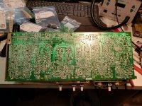
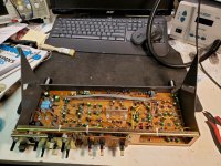
More recapping, just missing a few finally, and a lot of cleaning. The residue on the back of these boards seems like it's solder flux, but that would be uncharacteristically messy for Otari. It is very soluble in isopropyl alcohol.
There is nothing vaguely similar in the 50N II so I have to assume it's something else.
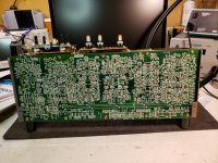
I've spent a lot of time dealing with the peripheral corrosion damage.
Looking forward to putting it back together and determining whether it runs correctly, if not some troubleshooting will follow. Hopefully the remainder of the capacitors (4 pieces, 3 values) will arrive in the next couple of days from DigiKey.
There is nothing vaguely similar in the 50N II so I have to assume it's something else.
I've spent a lot of time dealing with the peripheral corrosion damage.
Looking forward to putting it back together and determining whether it runs correctly, if not some troubleshooting will follow. Hopefully the remainder of the capacitors (4 pieces, 3 values) will arrive in the next couple of days from DigiKey.
Attachments
Well, if LF EQ pots DO produce "distortion" as you say, then it's on every record ever made from the fifties through the nineties (give or take). So it must not be very noticeable! 🙂Those pots in that particular implementation generate some measurable distortion. I was never taught that a pot was as stable or repeatable, or as free of contact issues, thermal drift, etc as a pair of resistors. It's convenient and that's it.
So what is your position on 741 like op-amps in the audio path? Am I opening a can of worms? 😛 I do worry about the decoupling scheme and the possibility of oscillation as well as wasting money on a meaningless "improvement"
I DO think that replacing '741-like' opamps with modern high-performance ones (LM4562) is worthwhile.
Hi Kevin,
Anyway, they aren't as bad as your comment might suggest. They do make things like that tape machine a possibility. Can you imagine adjusting a circuit where adjustments are interactive with another? Plenty of circuits where that is true. Adjusting with fixed resistors? It's bad enough with pots!
I think the tape has more variabilities than a pot. They are certainly not convenient and that's all. As far as distortion generated in a pot, yes that is true depending on the pot. There are good ones and bad ones. Guess which cost more?
At any rate, it comes down to making reasonable decisions with your components. BTW, do you plan to replace every resistor with units made by Dale? How about the ones that deal with bias frequencies? These questions aren't a challenge to you, just examples of the decisions that need to be made while keeping other considerations in mind. Reasonable choices in other words. 🙂
-Chris
Well... within reason, pots are plenty stable. I have some very expensive voltage references that use restricted range pots for every range. These are stable and quite frankly, make this high accuracy reference possible. Can you imagine adjusting everything with fixed resistors? We couldn't afford to buy any piece of sound equipment. While it is true that controls can be designed in in such a way as to be unreliable, that is a fault of the designer, and /or selection of the wrong part for the application. There is a lot of equipment that lives depend on that have pots (or semi-fixed resistors) in order to be adjusted to a proper operating range.I was never taught that a pot was as stable or repeatable, or as free of contact issues, thermal drift, etc as a pair of resistors. It's convenient and that's it.
Anyway, they aren't as bad as your comment might suggest. They do make things like that tape machine a possibility. Can you imagine adjusting a circuit where adjustments are interactive with another? Plenty of circuits where that is true. Adjusting with fixed resistors? It's bad enough with pots!
I think the tape has more variabilities than a pot. They are certainly not convenient and that's all. As far as distortion generated in a pot, yes that is true depending on the pot. There are good ones and bad ones. Guess which cost more?
At any rate, it comes down to making reasonable decisions with your components. BTW, do you plan to replace every resistor with units made by Dale? How about the ones that deal with bias frequencies? These questions aren't a challenge to you, just examples of the decisions that need to be made while keeping other considerations in mind. Reasonable choices in other words. 🙂
-Chris
Hmm,
You will rarely see a pot in a really modern piece of test equipment. I know because I spent some years designing ATE hardware for semiconductor testing and other purposes. Yes they run calibration routines at start up (and other times as needed) and use precision voltage sources and resistors for calibration. Calibration hardware is checked against NIST traceable standards at least on a yearly basis.
You hit the nail on the head though when you mentioned "restricted range" and most likely uses cermet or some custom high stability resistive element.
The pots used in the Otari decks are cheap crap (carbon track on phenolic) and the particular implementation Otari used generates measurable distortion, since it is a set once and forget proposition - for a guy like me it makes some sense to eliminate that pot.
I was talking in a very narrow and specific sense, you'll notice that I did not remove any other pots.
The Studer A810 uses multiplying DACs instead of pots for calibration and on the record side can be calibrated for two different types/brands of tape. Good, restored A-810s are very expensive and probably a little out of my league maintenance wise over the long term which is why I am currently playing with the much cheaper Otaris. The MX-5050 is rugged, but even in good shape is seriously mediocre sounding, and is seriously overrated by its fans - the MX-50, MX-55, and MTR-10/12/15 are much better machines. (In terms of tape handling and sound quality)
There is a lot of misinformation out there on Otaris and probably most other decks too. One popular misconception is that the MX-50 and MX-55 are older than the MX-5050.. The 5050 in it's earliest incarnations (the mini-pro) is more that 14 years older than the original MX-50N which was introduced in 1988. I was disturbed to read this on the tape project pages and see that no one ever correct this errant poster. The MX-50/55 are contemporary of late BII and BIII. The BIII borrows heavily from the original MX-50.
Truthfully I think the deck most people should be on the look out for in the Otari product mix is the 50. (The 55 is in another league and is expensive and rather rare these days.)
Well, if LF EQ pots DO produce "distortion" as you say, then it's on every record ever made from the fifties through the nineties (give or take). So it must not be very noticeable! 🙂
I DO think that replacing '741-like' opamps with modern high-performance ones (LM4562) is worthwhile.
I was speaking very specifically about Otari's implementation and choice of pot. Do I really have to be THAT specific to avoid people generalizing my aversion to that one pot to everything else??? 😛 Oh right this is the internet.. LOL I know you are pulling my chain and actually have added a lot positively speaking to the conversation...
My concern about the LM4562 is I suspect the decoupling (global, none local to any op-amp) and some of the other cost cutting measures used might result in hard to tame HF oscillations which is why I have not changed any of the op-amps to date.Take a look at the input circuitry in some stages of the MX-5050 or 50N and I am sure you will see a few things that while clever give you at least slight pause.. 😀
I do have a test bed audio module for the MKIII so that seems like the place to test and remediate those problems rather than in the one I use every day.
I suspect the 5532 would be a better device in most locations than the 4560, but not quiet enough to replace the NJM2043D (selected) in the first stage of the tape amp. I have also thought about the 4580 (also suggested by a friend) and possibly the OPA1642 on home brewed adapters - the low offset may allow some simplification without ending up with pops when switching modes - not quiet enough for low level use.
Attachments

Hi Kevin,
Example, the HP 3457A, 3458A 3478A and 34401A are all closed case calibration. The new meter I just got (Keysight 34465A) goes one step further and I think keeps the voltage reference powered up when the rest of the meter is off - enhancing accuracy. Most of the newer test equipment products do have internal standards which allows it to calibrate itself for some things, but that started with the ancient HP 3585A that constantly calibrates out offsets and other things. It runs these routines periodically without input from the operator.
For op amps in the head amp function, you can try the OPA2134. It is a J-FET input op amp, but may actually end up quieter than the NJM parts. The LME49720 / LM4562 would also be an excellent choice.
-Chris
Absolutely, but the reason is actually more about speed (closed case calibration) which allows the ambient temperature inside the case to remain unchanged. Also, as you've pointed out, the use of e-pots allows some calibration routines to be run automatically. A really nice touch.You will rarely see a pot in a really modern piece of test equipment. I know because I spent some years designing ATE hardware for semiconductor testing and other purposes. Yes they run calibration routines at start up (and other times as needed) and use precision voltage sources and resistors for calibration. Calibration hardware is checked against NIST traceable standards at least on a yearly basis.
Example, the HP 3457A, 3458A 3478A and 34401A are all closed case calibration. The new meter I just got (Keysight 34465A) goes one step further and I think keeps the voltage reference powered up when the rest of the meter is off - enhancing accuracy. Most of the newer test equipment products do have internal standards which allows it to calibrate itself for some things, but that started with the ancient HP 3585A that constantly calibrates out offsets and other things. It runs these routines periodically without input from the operator.
For op amps in the head amp function, you can try the OPA2134. It is a J-FET input op amp, but may actually end up quieter than the NJM parts. The LME49720 / LM4562 would also be an excellent choice.
-Chris
As far as choice of opamps for tape playback, a lot depends on the source impedance of the playback head. I can't find figures for Otari heads---anyone? For other manufacturers, I see data all over the place---from 35Ω to 4.4KΩ @ 1 Khz. The lower source impedance would call for a bipolar device (LM4562); the higher needs an FET (OPA2134). The modern, faster opamps can pose oscillation problems, but I think putting a 0.1 µF ceramic cap across pins 4 & 8 (power pins) should cure it. This could be easily tacked across the solder side of the board.
I am wondering where you got your information as to the history of Otari tape machines---??? Mine is an MX-5050, albeit a 1/2", 8 track. Not sure of its origins or date of manufacture.There is a lot of misinformation out there on Otaris and probably most other decks too. One popular misconception is that the MX-50 and MX-55 are older than the MX-5050.. The 5050 in it's earliest incarnations (the mini-pro) is more that 14 years older than the original MX-50N which was introduced in 1988. I was disturbed to read this on the tape project pages and see that no one ever correct this errant poster. The MX-50/55 are contemporary of late BII and BIII. The BIII borrows heavily from the original MX-50.
Hi dotneck335,
You go by the source impedance, but in the end it always comes down to trying the candidates.
The OPA2134 and it's brothers are unity gain stable and don't pose any problems for stability unless the layout is bad from the start. However, when changing op amps you would always "have a look" with a scope at least.
-Chris
I am wondering where you got your information as to the history of Otari tape machines---??? Mine is an MX-5050, albeit a 1/2", 8 track. Not sure of its origins or date of manufacture.
Manuals (in pdf only so far) and production dates mostly, some press releases, and exposure to a comparatively small number of their decks in addition to the ones I own. I have '83 and '88 MX-5050, and '90 and '94 MX-50s. (All confirmed by date codes on caps and other components.) I'm not sure of the exact transition date to MX-5050BIII but it would have been at least contemporary with the original 50N - so no earlier I guess than '88..
You can identify what year your machine was made by looking at the 2nd and 3rd digit in the serial #. I assume it is a MKIII-8 or MKIV-8? Or is it an earlier model? Interesting machines.
I've been offered a parts unit 50N and an MX-55 which I will look at this week-end. All of this of course begs the question of where I am going to store them.. LOL
The last caps required for the 50N recap arrived today, so tonight I will install them and start to put it back together. Hopefully I haven't broken anything..
As far as choice of opamps for tape playback, a lot depends on the source impedance of the playback head. I can't find figures for Otari heads---anyone? For other manufacturers, I see data all over the place---from 35Ω to 4.4KΩ @ 1 Khz. The lower source impedance would call for a bipolar device (LM4562); the higher needs an FET (OPA2134). The modern, faster opamps can pose oscillation problems, but I think putting a 0.1 µF ceramic cap across pins 4 & 8 (power pins) should cure it. This could be easily tacked across the solder side of the board.
Yes, in terms of decoupling that was what I was thinking.
Typical resistive loads on Otari playback heads is 110K, which leads me to believe they are relatively high impedance heads - likely 3 - 5K source impedance.
Interestingly they use the NJM2043 which is a bi-polar op-amp and essentially just a low noise version of the 4558 which is a pretty mediocre device. Given the circuit design I am surprised that current noise is not substantially degrading the SNR, but these machines are comparatively quiet or I am deaf or likely both. 🙂
I believe the NJM2043 is around 3-4nVrtHz @ 1kHz and the 5532 is around 5nVrtHz so I guess that's not a good idea. The LM4562 might be a dB or so quieter than the 2043 input currents are much lower which given the circuit design would not hurt.
- Home
- Source & Line
- Analogue Source
- So you think you want to play with tape: An Otari Story