Turns out during the last round of cap replacement in the MKIII-2 I managed to wick out the solder on one leg of the JFET that switches in the IEC 15ips playback EQ on the left channel. This led to some interesting symptoms, but I suspected it was in the EQ switch block and that's where it was and I found and fixed it quickly.
Deck survived 5 hours of continuous operation at high speed without capstan motor issues.
Recorded and played back at 15ips, the results were good. Compared the unmodified BII-2 which performed quite poorly by comparison, so having validated the changes and need for cap replacement in the MKIII-2 I will soon proceed to apply the same changes in the BII-2.
Attachments
Kevinkr
I have an Otari 5050 and am very interested in playback electronics. But first I want to build a couple of Alpha 20's to drive my open baffle speakers. I have the pcb for Bruno's BPBP, thinking about His Master's Noise phono-pre as I'd love to have an all DIY system.
Jazzfan
I have an Otari 5050 and am very interested in playback electronics. But first I want to build a couple of Alpha 20's to drive my open baffle speakers. I have the pcb for Bruno's BPBP, thinking about His Master's Noise phono-pre as I'd love to have an all DIY system.
Jazzfan
Cool, the modification details are here in the thread. There will be more.. 🙂
Eventually I plan to design and build a replay amp and compare to the modified circuitry in the Otari. (Lots of stuff in the way I need to deal with first.)
Eventually I plan to design and build a replay amp and compare to the modified circuitry in the Otari. (Lots of stuff in the way I need to deal with first.)
Here is a clean looking, unserviced BII-2 that so far looks like a bargain. Description seems to indicate it is a runner. Nice back story too..
Otari MX5050 BII 2 Tape Machine Reel To Reel Studio Recorder Pro 2 Track | eBay
Not affiliated with and don't know the seller, but this looks like an opportunity for the right person.
Otari MX5050 BII 2 Tape Machine Reel To Reel Studio Recorder Pro 2 Track | eBay
Not affiliated with and don't know the seller, but this looks like an opportunity for the right person.
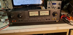
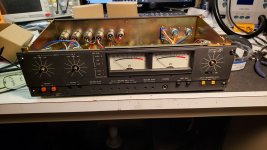
Mods to my BII-2 were completed successfully. This was a full recap of the audio module with a significant number of modifications around removing features and functionality I am not ever going to use. (The SEL REP function and output level switch.) Meters are relamped with 4 warm white LEDs each.
Attachments
MKIII-2 Attenuator upgrade
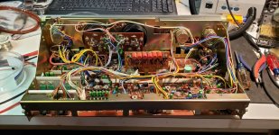
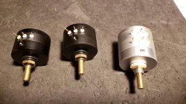
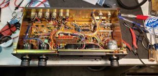
Today I replaced the last of the capacitors I missed previously, and I fitted the EIZZ attenuators I mentioned in a previous post.
The shafts as I suspected are a bit too short (unfortunate) and I have ordered some shaft extenders and some shaft material. There is enough clearance (only just) for the collars, once I get them I will decide whether I am using new knobs or modifying the originals to work with the extenders.
The original pots are pretty crappy ALPs garden variety logarithmic pots, the attenuators seem subjectively to be an improvement. (Subjective blather follows: cleaner, more spectrally balanced presentation, less emphasis on highs.) I have not done any measurements before or after so I do not know how much is expectation bias or an actual measurable improvement in linearity, response flatness, etc.
Attachments
Hi Osvaldo,
Thank you for your kind words.
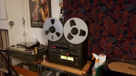
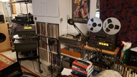
The gauge you see is actually an air pressure gauge as both of my turntables have Eminent Technology air bearing tonearms on them.
They operate at an air pressure of approximately 7psi (48.3 kilo-pascals).
Thank you for your kind words.
The gauge you see is actually an air pressure gauge as both of my turntables have Eminent Technology air bearing tonearms on them.
They operate at an air pressure of approximately 7psi (48.3 kilo-pascals).
My apologies by my ignorance, I never saw such a thing.
In other things, the tape players you "refurbished" have their own power amplifiers and speakers, or you use them with external cabinets and amplifiers?
I only saw at my face one of those machines, a ½tube ½ transistor AKAI unit that in the Radio Club we used to info interchange.
In other things, the tape players you "refurbished" have their own power amplifiers and speakers, or you use them with external cabinets and amplifiers?
I only saw at my face one of those machines, a ½tube ½ transistor AKAI unit that in the Radio Club we used to info interchange.
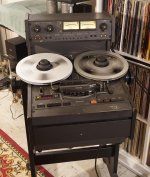
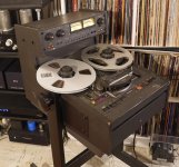
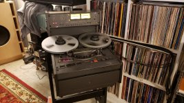
No they don't have power amps or speakers, the MX-5050 series were typically used in radio stations, small studios, advertising agencies and the like. They would typically be plugged into a mixing board of some sort. All balanced I/O on XLR connectors - they are connected to a switcher and hence to the balanced inputs on my line stage.
Some machines do have a tiny monitor speaker, but these do not. (Some versions of the MX-50 deck do have a single lo-fi monitor speaker)
The MKIII-2 came out of a radio station on Cape Cod, and the BII-2 came out of a recording studio owned by a local ad agency. (They made radio spots)
These would have been used for program playback in radio stations, mastering in 2nd/3rd tier recording studios for demos, etc.
They were generally too expensive to be considered for home use except for the occasional well healed audiophile not willing to reach for a Studer (much more money)
The MX-5050 in all incarnations is quite common around here, and came in many variants with up to 8 tracks on 1 inch tape.
I got some better hub adapters and the locks required to keep them from falling off.
It looks like I need to do the stepped attenuator conversion on this deck too at some point. Maybe different heads too.
Attachments

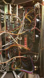
A general question if I may..... when you re-capped the pcb boards .. did you use a de-soldering gun or a de-soldering braid? I am assuming the pcb's are about 40 yrs old and could be very hard to replace if something were to go south ( lifting a pcb trace).
Please keep on posting your refurbishment process..
Please keep on posting your refurbishment process..
I use braid, I've never had good luck with the gun.. And yes the boards are moderately fragile, and I did have to repair the results of some wretchedly incompetent prior repair attempts with lifted traces on the logic PCB of my BII-2.
I lifted not a single trace in the process of recapping and modifying. (I have a lot of experience doing this)
Boards do become available from time to time on eBay for real basket cases, but it is catch as catch can.
I lifted not a single trace in the process of recapping and modifying. (I have a lot of experience doing this)
Boards do become available from time to time on eBay for real basket cases, but it is catch as catch can.
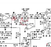
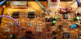
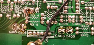
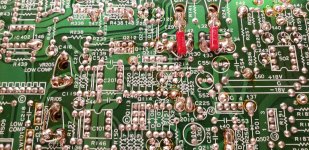
Yesterday I decided to investigate the Low Compensation circuit in the playback path, as I suspected the circuit was in bypass mode.
The pot however provides a connection to the inverting input of the op-amp through its wiper and what looks like approximately 1/4 of its end to end resistance. I wasn't too thrilled with the approach, and jumpered the terminals together.
This is resulted in perhaps the largest subjective improvement of any individual change made to date. (I have a strong suspicion the reduction in distortion would be measurable)
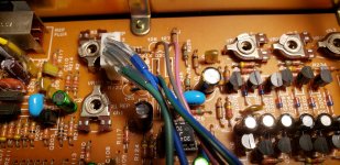
I also installed a pair of 100K resistors to compensate for the stepped attenuators being 25K rather than 20K, adding the attenuator slightly upset the calibration of the SRL setting which needs to be reasonably accurate for record calibration. Since I don't have a calibration tape and am lazy (no calculations required and no possibility of an error) I stuck a set of 100K resistors in there instead. (The original pot which I still have was close to 20K on both sides.) So done..
On the record side I removed 4 input caps on line input since I don't expect to see DC at the inputs. (Other than due to this op-amp's bias current and input offsets) This modification is likely of limited benefit.
I plan to eventually acquire calibration tapes and remove support for both 3.75ips recording and playback, but will not attempt it without calibration tapes as it is possible the frequency response of the other speeds may be slightly affected and will need adjustment.
The pot however provides a connection to the inverting input of the op-amp through its wiper and what looks like approximately 1/4 of its end to end resistance. I wasn't too thrilled with the approach, and jumpered the terminals together.
This is resulted in perhaps the largest subjective improvement of any individual change made to date. (I have a strong suspicion the reduction in distortion would be measurable)
I also installed a pair of 100K resistors to compensate for the stepped attenuators being 25K rather than 20K, adding the attenuator slightly upset the calibration of the SRL setting which needs to be reasonably accurate for record calibration. Since I don't have a calibration tape and am lazy (no calculations required and no possibility of an error) I stuck a set of 100K resistors in there instead. (The original pot which I still have was close to 20K on both sides.) So done..
On the record side I removed 4 input caps on line input since I don't expect to see DC at the inputs. (Other than due to this op-amp's bias current and input offsets) This modification is likely of limited benefit.
I plan to eventually acquire calibration tapes and remove support for both 3.75ips recording and playback, but will not attempt it without calibration tapes as it is possible the frequency response of the other speeds may be slightly affected and will need adjustment.
Attachments
-
 Low_comp_delete.png268 KB · Views: 380
 -
 Mic_delete_rwk_line_input_20190615.png607.7 KB · Views: 369
 -
 20190615_175711.jpg654.7 KB · Views: 202
 -
 20190615_175653.jpg690.4 KB · Views: 186
 -
 20190615_173740.jpg643.3 KB · Views: 375
 -
 20190615_173728.jpg950.8 KB · Views: 373
 -
 20190615_180635.jpg842.7 KB · Views: 217
Hi Kevin,
For years, I have used both braid and a desoldering pump (solder sucker) - the large ones with ribs. The nice thing about the pump is that it sucks away most of the heat with the molten solder. As long as the iron tip doesn't sit on the pad, chances are high you will not cause any additional damage, or damage to start with. I use flux and braid for cleanup work Follow that with solvent (I use lacquer thinner) and the board should look factory fresh, or close to it.
As for the gun, I used a desoldering station for a while. It's been in a box for decades now as it was more trouble to clean after every use than it helped. If I ever got a large number of solder pads to clear, I might drag the thing out, but it may not even work by now.
Losing the 3.75 ips speed is pretty reasonable. There is nothing of any quality recorded that slowly. If memory serves, there was an EQ change between 3 3/4 ips and 7 1/2 ips. 7 1/2 and 15 ips use the same EQ and 1 7/8 and 3 3/4 also use a different common EQ. So losing 3 3/4 is really going to simplify things for you.
Do you have any recorded tapes with cal tones recorded near the head end? You could use those to set yourself fairly closely to standard. That's what they are for, but to adjust playback exactly to the recording machine. You might want to see if you can grab some "masters" if they ever come up from no-name bands done in real studios. Just a thought in case you ever see anything like that.
-Chris
People keep telling me this, but it's not correct given that I only play and record using IEC. (NAB is basically obsolete except for playing old tapes)
IEC @ 7.5ips is 70us and ∞
IEC @ 15ips is 35us and ∞
I don't use NAB at all but it is true that the EQ is 50us and 3180uS for both speeds.
I refer to the standard tape manual (from standard tape laboratory) when in doubt. Lots of tables.
I'm very comfortable with my de-soldering technique and almost never lift pads, did not lift a single pad despite doing around 700 de-solder operations between these two decks. I have not done as well with a bespoke de-soldering tool and no longer have it as a result.
Hi Kevin,
Fair enough. Most of my real experience came from Studios using NAB. The semi-pro machines were all IEC, and I never did study that in detail as I did with NAB.
Thanks for reminding me or I might have bought NAB test tapes.
I have no doubt that you can desolder things successfully using braid only. I was only trying to show you could greatly reduce your costs with a solder sucker. I tried to point out that the only time damage occurs is when the tip moves on the pad in hopes you might try it again some day. For me, I use braid for two things. To get solder in places where I can't get the solder sucker, and to clean up the traces after extracting the parts. Saves me a fortune in braid! I rework a lot of connections every day. If you don't, then it might not be a concern for you.
Braid nearly always works. But the down side is possibly overheating components or the PCB. Polystyrene caps would be vulnerable to this for example. But, I was not, and am not passing judgement on your methods Kevin.
-Chris
Whoa there!! You're leaving out the guys who invented the whole damn thing anyway---AMPEX !!. They made the finest of machines and were built to be serviced for years.From what I see there, the Otari was similar to some of the Tascam machines in build except no bridge. So electronic improvements to the Otari would also apply to the Tascam and maybe even Revox and Studer. That encompasses pretty much every member who is interested in tape.-Chris
- Home
- Source & Line
- Analogue Source
- So you think you want to play with tape: An Otari Story