Hi Osvaldo, nice to see the photos of your build, my compliments.
Some of your comments don't coincide with how I understand the circuitry.
The transfer functions of the basic buck derived circuits have no R. Half Plane zeros (and are stable) so they are minimum phase, hence no time delay.
The boost derived circuits do have a RHP zero and are therefore not minimum phase.
The RHP zero always complicates (and makes worse) the control loop.
The simple explanation is, that to increase the output volts we first have to increase the current in the input inductor, so we turn the switch transistor ON - but this removes any power input to the load - just the opposite of what we want instantly.
Whereas a buck circuit that needs increased output volts, we just turn on the switch transistor and power starts to flow to the load immediately.
So I don't quite understand your view of this, but I don't have the theory of current mode control clear in my mind so perhaps I miss some aspect.
Thanks for the chance to think this over.
Best wishes
David
Some of your comments don't coincide with how I understand the circuitry.
This is not quite correct, there is no "time delay" in a low pass filter that is minimum phase.There are mainly two kinds of SMPS: those derived from the Buck and those from Boost.
Buck derived (Buck, Forward (single and double MOSFET), Half and Full Bridge) are the worst choice...Viewed from the PWM control chip this is a low frequency pass filter with an inherent time delay to mantain the output volt...But they are slow correction devices for load...
The transfer functions of the basic buck derived circuits have no R. Half Plane zeros (and are stable) so they are minimum phase, hence no time delay.
ITOH the derived from boost topology and mainly the Fly Back (single and double MOSFET) are inherently higher speed because they use a much smaller inductor in the primary side that with current mode SMPS (UC384x and similar) completely dissapear from the transfer equation, remaining only the ouput caps. As they usualy have higher RF ripple, usually a small pi filter is used but its time constant and time delay are noticeably lower than buck, making them quicklier response than those. The Boost deriver are thus, clearly, the best option.
The boost derived circuits do have a RHP zero and are therefore not minimum phase.
The RHP zero always complicates (and makes worse) the control loop.
The simple explanation is, that to increase the output volts we first have to increase the current in the input inductor, so we turn the switch transistor ON - but this removes any power input to the load - just the opposite of what we want instantly.
Whereas a buck circuit that needs increased output volts, we just turn on the switch transistor and power starts to flow to the load immediately.
So I don't quite understand your view of this, but I don't have the theory of current mode control clear in my mind so perhaps I miss some aspect.
Thanks for the chance to think this over.
Best wishes
David
You are right, but I was comparing with flybacks with duties less than one. If the load demands duty over one, obviously it collapses.
In any case what you said don't coincide with what I learnt and my experience. Take for example a look to the datasheets of newer IC for SMPS for example L497x from STM who uses regulation in forward mode (they sense the input to the regulator toguether to output) and compensate the output immediately in place of wait to a sag or bump in the output voltage. This is because of the time delay in the output filter.
In any case what you said don't coincide with what I learnt and my experience. Take for example a look to the datasheets of newer IC for SMPS for example L497x from STM who uses regulation in forward mode (they sense the input to the regulator toguether to output) and compensate the output immediately in place of wait to a sag or bump in the output voltage. This is because of the time delay in the output filter.
Dave is correct about the Right Half Plane Zero, RHPZ, and its impact on loop bandwidth. However Osvaldo is also sort of correct assuming they are operating their convertor with discontinuous current, always returns to zero before the next switching cycle begins. The penalty there is an increase, up to four times and more, of the peak inductor current. Under those conditions the RHPZ is not present. It appears when the convertor enters continuous conduction and varies with the load. Voltage Feedforward as implemented in the L497x is used because it is a Voltage Mode Controller. Disturbance or delay at the output is not what is being corrected. It is changes in the input. Note that the voltage feedforward is tied into the timing capacitor so that the ramp amplitude, and slope, matches the input voltage. This acts to make the modulator gain insensitive to changes in input voltage. With current mode control voltage feedforward is inherently present. Generally speaking a buck convertor, voltage of current mode control, can be operated with a closed loop response up to Fs/2PID, Fs is the switching frequency D is the operating duty cycle. I won't state for sure but it is likely that a flyback with discontinuous operation should be able to operated to a similar crossover frequency but it's game over if it enters continuous current operation and the RHPZ rears its ugly head. This is small signal stuff so there may be some mileage in thinking about transient behaviour, how fast the convertor can slew the inductor current, but in both cases this is largely determined by the size of the inductor, smaller is faster, and large signal dynamics of the control loop. How it behaves going into and coming out of saturation.

Feed-forward is not subject to some of the unavoidable limitations that apply to all feedback system, so it is potentially useful to assist any feedback system.Take for example a look to the datasheets of newer IC for SMPS for example L497x from STM who uses...forward mode (they sense the input...) and compensate the output immediately...
So no surprise that it is used in the latest Buck ICs.
You raise a reasonable point if it is not used in Boost ICs, maybe they don't need it so badly.
I suspect another reason, that it doesn't work well with the RHP zero inherent in the Boost circuit.
For isolated SMPS, I think the transformer ratio can be used to make either buck or boost possible.
But the buck versions (Full or Half B.) are preferred, and very much so, AFAIK.
If the boost implementation was better then wouldn't it be picked?
I am not a "supporter" of any particular circuitry (as if it was football and I don't like your "Boost" team!)
Actually, I have tried to develop a nice Cuk converter but it has the RHP zero that comes with Boost transfer function.
And I found it difficult to produce satisfactory feedback loop response.
That is why I was interested in your comments.
Best wishes
David
Cross-posted with reply #143, so some of my comments are already answered.
Last edited:
The feed forward concept is very old. Since the tube era very early in 1940's there was an idea of feeding a sample of the input voltage to the pentode voltage amplifier screen's or to the upper grid if cascode is used. I myself did a linear regulator with a 6FM7 and 6U10 with dual triode cascoded. I took a good supply reasonably free of ripple and inserted in series with the regulator the seconday of a transformer whose primary was feed from a variac with controllable amount of '"ripple". A fraction of this DC + AC was feed to the upper cascode' grid. Adjusting the proper amount via a preset, the ripple at the output was really negligible unless the AC was so high to make series pass to run dry of plate voltage.
I also made an experimental tube SMPS that is published here some years ago.
I also made an experimental tube SMPS that is published here some years ago.
If you measure voltage before inductor. Isnt the power distributed with respect to duty cycle. Voltage there is independent of power delivered. How can it stablise voltage if voltage is independent.
It will depend on load conditions that finally affects the Q of such resonant circuits. Also the ESR of the capacitors interfere in the problem.
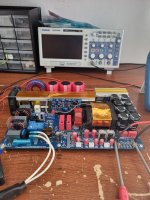
Yes its a resonant converter, the continuous power its 3kwIts a resonant converter plus PFC. Interesting. By its size; appears to be 1KW more or less.
Purchased or your own development?Yes its a resonant converter, the continuous power its 3kw
More details please!
Best wishes
David
Last edited:
And whats the idea with such a SMPS? Its too big for audio purpouses at home. What output voltages/currents is capable?
I had repaired several like this one, but green painted and designed specifically to drive large UV lamps to water purification. I don't remember the TM but were from Germany.
I had repaired several like this one, but green painted and designed specifically to drive large UV lamps to water purification. I don't remember the TM but were from Germany.
Its made by me and its capable for about 3kw output. Yes for home its to big but for my hobby its too small 😅 , in this moment it's used in class D amplifier, the output its limited by PFC ( I used 3.5kw PFC)
Also I can change the output voltages by modifying the turn ratio on transformer
Also I can change the output voltages by modifying the turn ratio on transformer
- Home
- Amplifiers
- Power Supplies
- SMPS in audio