They vanished - maybe you'll find them in another worldAye voltwide...these irish eye's are smiling that you appreciate me contribution,
however wee bit it may be.
Now, ware did those fairies goe 'cause I want me pot o'gold.
Cheers,
Please pardon me to revive this thread but i want to try to repair a Littlemark II next week. This will be my first SMPS repair - i know about the dangers of high voltage and be very careful as always!
I don't have it on the bench yet but i was reading the schematics carefully and i saw that there is no fuse between the SMPS and the 80V Rails. Doesn't that make the SMPS MOSFETS blow if the Poweramp Transistors short? Would it be possible to insert a fuse?
I don't have it on the bench yet but i was reading the schematics carefully and i saw that there is no fuse between the SMPS and the 80V Rails. Doesn't that make the SMPS MOSFETS blow if the Poweramp Transistors short? Would it be possible to insert a fuse?
In the meantime i managed to repair it. My first real SMPS Amp Repair! Yay!
It was quite straight forward.
1. No blown fuse!
2. I checked the voltage Rails on the Amp side --> Nothing.
3. I checked the power Mosfets --> okay (have to replace the unfortunately because i cut the legs for easier desoldering)
4. I checked the IR21531D for Power --> no Voltage between PINs 1 and 4 (btw. on the schematic they are wrong ! switched 1 and 4!)
5. Checked the power line from SMPS caps to the ic, found a dead resistor (R78 had failed open)
6. Replaced R78
7. Soldered in the "damaged" Mosfets just for Testing
8. WORKING!
Conclusion: Next time i will check the vcc and gnd of all active elements first!
But now it's still on my bench. What could i do to save it from the usual mosfet blow?
And another question:
1. Do i have to match or adjust some resistor values for the replacement SMPS Mosfets?
2. Is it useful to insert a fuse (what value would you recommend) on the +-80v rails.
1. Do i have to match or adjust some resistor values for the replacement SMPS Mosfets?
2. Is it useful to insert a fuse (what value would you recommend) on the +-80v rails.
Hi there.
A friend brought me a Little Mark for repair.
So far I found two power amp MOSFETs and the two SMPS MOSFETs dead.
Also interested in questions raised by f0m3 if anyone has any clue or opinion 🙂
Thanks!
A friend brought me a Little Mark for repair.
So far I found two power amp MOSFETs and the two SMPS MOSFETs dead.
Also interested in questions raised by f0m3 if anyone has any clue or opinion 🙂
Thanks!
Hi,
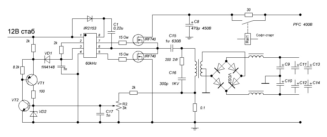
If you look at the schematic attached in the 3rd post of this topic, there is a pot (R2), from which the maximum output current is set. All that circuit - VT1, VT2, VD1, VD2 will shutdown IR2153 when the limit is reached (you can read about CT pin, in the driver datasheet).
I think that some fuses on the 80V rails would be redundant, at least.
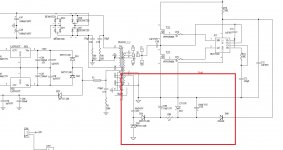
Thanks but unfortunately, the schematic was attached as a generic example of a working implementation. The real one can be found here: https://music-electronics-forum.com/attachment.php?attachmentid=37571&d=1453963798
There's not pot there, nor current limit for the power supply...
There's not pot there, nor current limit for the power supply...
In this diagram there is another method for limiting the current, also very efficient: a current transformer winding that will pull the driver voltage Vcc under 10V (so the driver stops) when the current rises above a certain limit.
I would recommend you to check the parts inside the red square.
I would recommend you to check the parts inside the red square.
Attachments
Sorry, but I'm pretty sure that is the running Vcc supply for the driver -- D40's cathode is toward the 2153.
R78, being 270K, provides only enough current to get the 2153 wide awake.
Regards
R78, being 270K, provides only enough current to get the 2153 wide awake.
Regards
All those parts have been checked OK 🙂
The question regarding the missing protection raised by f0m3 and I'm interested in are referring to the scenario described by Steve Smith, which is exactly what happened to the amp I've repaired. A faulty cabinet blew 2 output transistors and then the 2 power supply transistors. They were the 4 only parts I've diagnosed faulty and replaced.
The amp is working again 🙂
I wonder if there is a way to prevent the 2 expensive PSU MOSFETs from shorting in case it would happen again.
Also, I've replaced the 6 output MOSFETs with matched trios.
Does bias has to be adjusted (via TRIM1 pot) and how?
I'm not used to repair those modern designs, so any advice appreciated, thanks!
The question regarding the missing protection raised by f0m3 and I'm interested in are referring to the scenario described by Steve Smith, which is exactly what happened to the amp I've repaired. A faulty cabinet blew 2 output transistors and then the 2 power supply transistors. They were the 4 only parts I've diagnosed faulty and replaced.
The amp is working again 🙂
I wonder if there is a way to prevent the 2 expensive PSU MOSFETs from shorting in case it would happen again.
Over the past couple of years, I have repaired a few of these MarkBass amps.
The fault is usually that a pair of output transistors in the power amp blow and short out the power supply.
As MarkBass seem to have cut corners on the design and decided not to fit any fuses in the +/- 80v supplies or provide the switching power supply with any sort of current limit, the power supply responds to the drop in voltage of its output by working harder until it destroys itself by blowing its two power transistors.
On most of the amps I have repaired, changing the amplifier and power supply FETs has been enough to get them working again.
Also, I've replaced the 6 output MOSFETs with matched trios.
Does bias has to be adjusted (via TRIM1 pot) and how?
I'm not used to repair those modern designs, so any advice appreciated, thanks!
big output at secondary for ir2153 will cause in rush current in primary, as far as we know, ir2153 chip does not have soft start, so this chip will easy broken together with mosfet when facing huge inrush current by running +- 80vdc at output, at the same time when short circuit happen at secondary cause by amplifier or else, the primary chip together with mosfet easy to explode. there are few implementation to this chip need to be done, its not only ir2153 chip, any smps will have night mare exploding if secondary side or over current happening. You need to have softstart for this chip ir2153 family, plus ocp protection or better come together with over temp protection. the gate resistor is important too must be set correctly with mosfet you use and fsw setting, but.. never blow your chip and mosfet, use light bulb 40w for testing fault or for first time running. softstart is very critical when you have secondary high voltage and you put together big caps bank there. i have alot experience with ir2153 chips and now i dont fear them, this chip need softstart very badly and better come with ocp.
All those parts have been checked OK 🙂
..
Also, I've replaced the 6 output MOSFETs with matched trios.
Does bias has to be adjusted (via TRIM1 pot) and how?
I'm not used to repair those modern designs, so any advice appreciated, thanks!
Yes! Please adjust the bias. Every MOSFET (or trio of them) has a different threshold. Since that will directly alter the idle current, adjusting the bias may be the most important part of the repair.
If the service information you have at hand doesn't describe how, post back here and someone will surely be able to help.
Cheers
Obviously it isn't! No procedure or values.
I've read on an italian forum that Markbass replied that idle current must be between 40mA and 50mA. That's all.
I've read on an italian forum that Markbass replied that idle current must be between 40mA and 50mA. That's all.
OK, well, I have to hope others here will pipe up/in. I have spent a good bit of time studying lateral MOSsies and their use in audio output stages, but not much on 'regular', vertical MOSFETs. But it is well known that Gate thresholds vary widely, even within a particular p/n and mfg.
If you're fairly confident that 40 - 50mA is the proper value, that works out to 4,2 to 5,8mV per Source resistor (allowing for the full 10% likely range in value); but that seems a little light to me. On the other hand, 40 to 50mA per MOSFET seems a little heavy -- that's 24 Watts idling @80V rails. How much heat sink does it have? Maybe now would be a good time to post in the Music Instruments and Amps forum -- this isn't really a power supply question anymore, after all.😉
If you can forgive an aside . . This doesn't appear to be what I would call 'a very enlightened' design. It looks like every time a prototype blew, the designer just stuck in (a) bigger transistor(s) -- without applying the expertise or patience to address the cause of the failure. Just my 2 bits.
Regards
Last edited:
The elephant in the room is the output caps are all the wrong way around.
Yep, that too 😉 good catch (I missed it 😱)
Maybe the 4 that aren't actually connected didn't pop! 😀😱
Cheers
Maybe the 4 that aren't actually connected didn't pop! 😀😱
Cheers
Last edited:
I realise that this is an old thread but I have a Little Mark Tube for repair that keeps blowing fuses after being dropped. Where would you start?One other failure I have had with a MarkBass amp is one of the 10 ohm gate resistors only soldered properly at one end, making an intermittent connection at the other. When it disconnects, the FET floats somewhere between on and off rather than being turned off fully by the driver, and if it is in a conductive state when the other FET turns on, current flows through both and the fuse blows.
Steve.
A little unrelated to the repair maybe, but how do these guys got away with no PFC?
Or is this just an older model or something?
Or is this just an older model or something?
- Home
- Amplifiers
- Power Supplies
- SMPS failure. IR21531 - Please help