Hi guys,
My friend give me his broken mark bass amp. I checked, 220V fuse and mosfets are blown.
All other parts are fine. I changed mosfets irfp460, power on the amp and fuse blowned again.
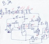
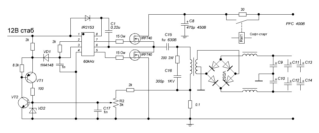
There are a driver ic on circuit. But numbers erased by manifacturer. Could i replace it with ir21531? If no, what type of driver can i use? Circuit at attachment file.
Please help me. Thanks.
Okan.
My friend give me his broken mark bass amp. I checked, 220V fuse and mosfets are blown.
All other parts are fine. I changed mosfets irfp460, power on the amp and fuse blowned again.
There are a driver ic on circuit. But numbers erased by manifacturer. Could i replace it with ir21531? If no, what type of driver can i use? Circuit at attachment file.
Please help me. Thanks.
Okan.
Attachments
The mosfets often take the driver IC with them.
I had this happen a few times on my early SMPS designs.
I can only guess you need to go through each 8 pin SMPS IC and see if any fit sensibly with the other components.
I had this happen a few times on my early SMPS designs.
I can only guess you need to go through each 8 pin SMPS IC and see if any fit sensibly with the other components.
It is highly possible to be IR21531. An oscilloscope is very useful when repairing SMPS.
I am not sure you follow these so i write:
-Connect a 60-100 W incandescent lamp in series with the mains line.
-Remove both IRFP460s and the output load by simly removing fuses if any, or output rectifier diodes at the DC output line.
-Check 12-15V DC Vcc voltage at Pin:1 of IC.
-Check the square wave amplitude and frequency at pin: 5 and 7 of IC. Must be 0-Vcc Volts, and you can find frequency that it should be from the page 3 > http://www.irf.com/product-info/datasheets/data/ir21531.pdf
-Everything is good, replace Mosfets, rectifier diodes and check output voltage.
-Output voltage is good, remove lamp and check again.
-Always follow this order when repairing SMPS, you will have less blows.
Last edited:
Thank you.
I have a tectronix 2445b 150 MHz scope. I didn't repair a spms with driver ic before.
In my other smps repairs, there are only blown mosfets and diodes. Check, change and go, it was simple. But now, i am learning new things. Thank you.
I check the datasheet again. I have Rt:18K and read 400pF on smd Ct capacitor. So, i must read a ~16 kHZ square wave. Am i right?
Lamp is a good idea, i am going to try it tomorrow. Today i will buy some irfp460s and driver ics from my component supplier, for blown again possiblity.
Thank you so much again, when i try, i will tell the results.
Thank you.
I have a tectronix 2445b 150 MHz scope. I didn't repair a spms with driver ic before.
In my other smps repairs, there are only blown mosfets and diodes. Check, change and go, it was simple. But now, i am learning new things. Thank you.
I check the datasheet again. I have Rt:18K and read 400pF on smd Ct capacitor. So, i must read a ~16 kHZ square wave. Am i right?
Lamp is a good idea, i am going to try it tomorrow. Today i will buy some irfp460s and driver ics from my component supplier, for blown again possiblity.
Thank you so much again, when i try, i will tell the results.
Looking at the chart given in the data sheet corresponding to 18K-400P, switching frequency must be around 100 KHz.
I know this is a late reply but I do not see any mention of use of an isolation transformer when connecting an oscilloscope to a smps circuit.
I know this is a late reply but I do not see any mention of use of an isolation transformer when connecting an oscilloscope to a smps circuit.
Thanks pinyoro, i know it. Also user nec3 warned me by pm.
But i didn't fix it yet.
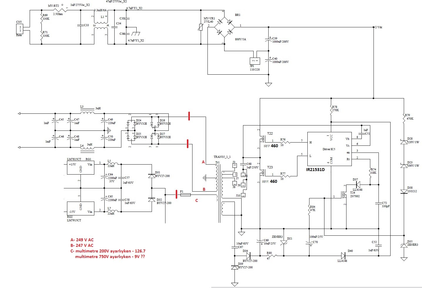
This is my schematic. I renewed mosfets and power on circuit after cut the red lines. No fuse blowing. Everything looks fine but when i measure A,B and C test points, readings are huge.
I measured between ground and this points.
A: 249V AC
B: 247V AC
C: -9V AC (when my multimeter set to 750V AC)
-126.7 V AC (when my multimeter set to 200V AC)
I don't have a Fluke, but mine is good, too.
Are these readings interesting? Too high? There are 63V caps, if i connect red lines, they can be blow up.
What's going wrong? Is this transformer failure?
Thanks all for your help.
Can You post some oscillograms from point A, B, C and from pin 5 of IR2153D?
Next, you probably need some bleeder resistors at the output. Put some value to get about 1W of power from PSU.
Regarding measurements with multimeters, forget that for AC measurements on SMPS, use only oscilloscope.
Next, you probably need some bleeder resistors at the output. Put some value to get about 1W of power from PSU.
Regarding measurements with multimeters, forget that for AC measurements on SMPS, use only oscilloscope.
I know this is an old thread, but someone might find it looking for information - like I did a while ago.
Over the past couple of years, I have repaired a few of these MarkBass amps.
The fault is usually that a pair of output transistors in the power amp blow and short out the power supply.
As MarkBass seem to have cut corners on the design and decided not to fit any fuses in the +/- 80v supplies or provide the switching power supply with any sort of current limit, the power supply responds to the drop in voltage of its output by working harder until it destroys itself by blowing its two power transistors.
On most of the amps I have repaired, changing the amplifier and power supply FETs has been enough to get them working again.
There have been a couple of exceptions. One amp was subjected to a transformer going over voltage for just half a second (until it tripped out). Judging by the lights which went a bit brighter, I would say from 230v up to 350v.
This amp blew the diodes in the +/- 80v rectifiers and then the power supply transistors.
Another amp blew the normal two amplifier transistors and the power supply transistors but wouldn't start up when they were replaced. The fault was found to be 15v zener diode D21 and diode D40 which were shorted out, ensuring that the IR21531D had no voltage to run from. Replacing these components.
I mentioned that one of these amps has been repaired by me three times. Two of those failures and one of another amp were within a couple of weeks and owned by the same person. I decided that this was too much to be a coincidence and looked for anything common. All we could find was that these amps all failed whilst connected to a MarkBass 2x10 + horn cab. They have been fine with a 1 x 18 cab.
The 2x10 cab has since been reported as crackling and cutting out occasionally when run from an Ampeg SVT. We concluded that the amps are failing due to a fault with the cab. I suspect the HF driver, but it needs more investigation.
Basically, these amps appear to be designed very badly with no protection. They are great when they are working but go wrong too easily. There is a specialist musical instrument repair person in my town. After talking to MarkBass and being put off by them, he won't touch them. MarkBass would rather you returned the amp for repair for an extortionate fee.
Steve.
Until I know from my readings in SMPS, half bridge topology (and push pull or full bridge) would need choke (Inductor) input filter after the rectifications. Perhaps the start up over a purely capacitive load causes faults.
One amp was subjected to a transformer going over voltage for just half a second
That should have been generator, not transformer.
Steve.
quite often the voice coils of the woofers have been overheated, and the insulation of the voice coil wire has been rubbed off. when driven hard the voice coil warps and a sudden short results when the wires short through the magnet pole. intermittent shorts can be quite destructive..
Is anyone else bothered by the lack of a snubber on the IRFP460's. Building those transformers with the leakage inductance very tightly controlled, at a very low level, would be a nightmare.
Of course we're a little behind the timeline catching up to this, but if there are still amps out there working -- or others designed by the same guys -- the ones with the leakier transformers have probably gone through a bunch of power FETs by now. And their owners are probably ready for some relief -- if they haven't already junked the darned things.
Just a thought. Seems like it might be worth a couple of 75 cent parts.
--Rick
Is anyone else bothered by the lack of a snubber on the IRFP460's.
A snubber (or two) is probably a good idea. However, all of the power supply failures I have repaired have been caused by something else failing first. Usually a pair of output transistors, or in one case, the +/-80v supply rectifiers.
All of the Little Mark II amps I have repaired had higher specification IRFP27N60 transistors in the PSU rather than IRFP460 which I have only found in a lower power model (can't remember the model name).
Steve.
Snubbers are not critical in this circuit because there is an AC couple capacitor in series with transformer primary. In other circuits without series capacitor, such as push-pull SMPS, the snubbers can play a key role in preventing core saturation (the half doing more magnetizing current will also do faster crossover and thus less volts*seconds, reaching an equilibrium as long as enough dead time and crossover time are provided).
Offline power supplies without enough protections are lame, because these are connected to the "outer world" through mains line, and exposed to "outer world" imperfections.
Offline power supplies without enough protections are lame, because these are connected to the "outer world" through mains line, and exposed to "outer world" imperfections.
One other failure I have had with a MarkBass amp is one of the 10 ohm gate resistors only soldered properly at one end, making an intermittent connection at the other. When it disconnects, the FET floats somewhere between on and off rather than being turned off fully by the driver, and if it is in a conductive state when the other FET turns on, current flows through both and the fuse blows.
Steve.
Steve.
Hi y'all, I find this interesting.
I just started working on a different smps and I'm in learning mode.
The OP hand drew is smps I think it's standard layout practice,
power in left to power out right.
Then the PFC400B, has power coming in on the right
and something on 12B upper left of schematic.
But, it almost looks like upper right and lower right
are the main line/neutral, with the smoothed output in the center.
That kind of threw me, but here it my question....
related but different...I have a quad out SMPS,
+5VD, +15V, -15V, +38V
Why on these series of power supplies do they
have the 8A bridge chip before the transformer?
Here is a link to pic of one that I have, that fried
on me. LINK
The actual layout is in from the lower right pic,
then follows Cap&fuse, MOV choke, MOV, cap Bridge,
mains Filter then transformer....
From the other pics...you can view it from the trace side of the board.
The thing is hi dollar too. 🙁
Question, where do you use the isolation tranformer? On the mains?
or is it between the O-Scope probes and the DUTs circuit?
Cheers,
Last edited:
- Home
- Amplifiers
- Power Supplies
- SMPS failure. IR21531 - Please help