Hi,
Am sorry but I didn't know about your skill. Just select the ohms option in the meter. Since the bridge it is already shorted remove it. To check the resistance put one test probe on the positive side of the cap and the other probe in the negative side of the cap. The meter should read at the beginning a low reading and then the reading should slowly read high. This is due to the capacitors charging up. A low reading means that there it is a short on the circuit. Another way you can read the resistance with one probe at the negative side of the bridge and the other probe at the positive side of the bridge.
Am sorry but I didn't know about your skill. Just select the ohms option in the meter. Since the bridge it is already shorted remove it. To check the resistance put one test probe on the positive side of the cap and the other probe in the negative side of the cap. The meter should read at the beginning a low reading and then the reading should slowly read high. This is due to the capacitors charging up. A low reading means that there it is a short on the circuit. Another way you can read the resistance with one probe at the negative side of the bridge and the other probe at the positive side of the bridge.
Hi,
Am sorry but I didn't know about your skill. Just select the ohms option in the meter. Since the bridge it is already shorted remove it. To check the resistance put one test probe on the positive side of the cap and the other probe in the negative side of the cap. The meter should read at the beginning a low reading and then the reading should slowly read high. This is due to the capacitors charging up. A low reading means that there it is a short on the circuit. Another way you can read the resistance with one probe at the negative side of the bridge and the other probe at the positive side of the bridge.
Thank you, I checked all the caps and they seem fine. I checked all the other components to make sure nothing is shorted to the ground plane. It all seems fine.
I guess I'll need to order another rectifier bridge to go any further.
Hi,
If you are going to buy a new bridge buy one that at least it is 3 amps. Like Mouser 3KBP005M-E4/51 = 3 amp 50 volts.
If you are going to buy a new bridge buy one that at least it is 3 amps. Like Mouser 3KBP005M-E4/51 = 3 amp 50 volts.
Hi,
Also I recommended you to add a fuse just in case. By adding the fuse it will blow it and not the bridge.
Also I recommended you to add a fuse just in case. By adding the fuse it will blow it and not the bridge.
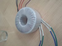
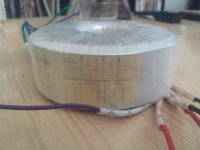
And here it is with 400VA (22+22V) transformer...
Just curious, did you power this up using a variac?
Or did you hook it up and flip a switch like I did?😱
I would suggest that you have got the secondary wiring confused.
I hope it's that simple.
I posted pics of the way I hooked it up. Nobody has said it's wrong but it certainly could be.
Attached is a pic of the other circuit I made a pcb for that behaved exactly like the Twisted Pear psu [this is why I don't doubt it's something I'm doing wrong]. You can see how I wired ths 2nd's if you look at the transformer pic.
On power up D4 popped and all the input traces got damaged.
If anybody sees anything wrong PLEASE let me know. Thanks!
Attachments
Geez Solving a Rubix cube is easier than solving this.
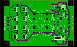
As the PCB circuit in the first pic states it should be wired up as Blue Green Green Blue.
Wiring it up as Blue Green Blue Green will act like a short circuit between the two bridges.
http://www.diyaudio.com/forums/twisted-pear/264381-smoking-bridges-2.html#post4112408
As you've posted here.. The wiring appears to be correct.
So this is invalid:
The mystery continues!
And.. The primary can't be wired up wrong, being an American the OP is running 120v not 240v. Wait a minute.... If the OP has the primary wiring wrong then that means there is half the voltage going through the secondary, so therefore there is twice the amount of amperage going through the secondary... So, OP, have you got the primary windings wired correctly?
This seems to be the only common factor here in the two power supplies. Both regulator boards have blown in fairly equal circumstances.
And these voltages seem a bit low for an open-circuit reading:
Make sure you disconnect the mains first before working on it!
*freax continues to blow bubbles through his corn cob pipe*
As the PCB circuit in the first pic states it should be wired up as Blue Green Green Blue.
Wiring it up as Blue Green Blue Green will act like a short circuit between the two bridges.
http://www.diyaudio.com/forums/twisted-pear/264381-smoking-bridges-2.html#post4112408
As you've posted here.. The wiring appears to be correct.
So this is invalid:
I would suggest that you have got the secondary wiring confused.
The mystery continues!
And.. The primary can't be wired up wrong, being an American the OP is running 120v not 240v. Wait a minute.... If the OP has the primary wiring wrong then that means there is half the voltage going through the secondary, so therefore there is twice the amount of amperage going through the secondary... So, OP, have you got the primary windings wired correctly?
This seems to be the only common factor here in the two power supplies. Both regulator boards have blown in fairly equal circumstances.
And these voltages seem a bit low for an open-circuit reading:
I get 16v off both sets of 2nd's when I keep them paired as in my last post.
12.5 and 13v if I mix the 2nd's
This leads me to believe it is important to keep them paired, but, would it cause the rectifiers to blow if they are mixed?
Make sure you disconnect the mains first before working on it!
*freax continues to blow bubbles through his corn cob pipe*
Last edited:
I believe the primarys are correct.
The two reds are twisted together and attached to Neutral
The two blacks are twisted and attached to Load.
I get 16v between each set of 2nd's
The two reds are twisted together and attached to Neutral
The two blacks are twisted and attached to Load.
I get 16v between each set of 2nd's
I believe the primarys are correct.
The two reds are twisted together and attached to Neutral
The two blacks are twisted and attached to Load.
I get 16v between each set of 2nd's
You should be getting 15-16vAC on each secondary winding.
You should be getting 15-16vAC on each secondary winding.
That's what I have. If I measure between blue and green I get 16v
That's what I have. If I measure between blue and green I get 16v
Right. So the problem is/was in the caps/voltage regulators.
This might be a good time to start afresh with some new kits.
If it still blows something there is a million to 1 chance that there is some kind of fault in the transformer. I know Antek, and they make really solid stuff. So this is why I'm giving it a million to 1 chance. Its practically like winning the lottery.
But the funny thing is, IF THERE WAS, you would've gotten a shock from the mains leaking through to the secondary while checking the voltages.
So the only logical thing is that the capacitors in both circuits were faulty. If you sourced them from Hong Kong then its a slim possibility.
Last edited:
Hi,
Just wire the side that it is blowing the bridge and let the other side open. See if it still blow the bridge.
Just wire the side that it is blowing the bridge and let the other side open. See if it still blow the bridge.
Hi,
You said that D4 popped when power it is applied meaning that you have a shorted around D3 cathode to ground. If D3 cathode it is grounded that will applied the AC thru D4 to ground. Check the solder around D3 cathode for solder bridge or check resistance between D3 cathode and ground. Low resistance means you have a short.
You said that D4 popped when power it is applied meaning that you have a shorted around D3 cathode to ground. If D3 cathode it is grounded that will applied the AC thru D4 to ground. Check the solder around D3 cathode for solder bridge or check resistance between D3 cathode and ground. Low resistance means you have a short.
I think the wiring to the secondaries should be B-G-B-G and NOT as marked on the board.
I think the error is that the transformer wiring colours do not match the board markings.
I think the error is that the transformer wiring colours do not match the board markings.
Hi,
You said that D4 popped when power it is applied meaning that you have a shorted around D3 cathode to ground. If D3 cathode it is grounded that will applied the AC thru D4 to ground. Check the solder around D3 cathode for solder bridge or check resistance between D3 cathode and ground. Low resistance means you have a short.
BINGO!! D3 cathode is shorted to ground. Good call!
Still not sure what happened with the other board but I'll get some new bridges for that one and see what I can get.
Thanks for all the help!
I think the wiring to the secondaries should be B-G-B-G and NOT as marked on the board.
I think the error is that the transformer wiring colours do not match the board markings.
Correct!
http://www.diyaudio.com/forums/twisted-pear/264381-smoking-bridges-2.html#post4112232
Brian's wiring is correct.
This is what happened to the other board.
So to proceed from this, all you need to do is check the traces of the PCB and renew them if necessary, and replace the bridge rectifiers. And wire them up as Brian has done.
I was wrong twice! wow.
Last edited:
OK! Second mystery solved. I just wired the Twisted Pear board wrong. 😱
Its ok I would've made the exact same mistake. This should be a lesson to everyone that Color coding is never trustworthy.
Dual voltage regulator circuits make me nervous even at the best of times.
- Status
- Not open for further replies.
- Home
- More Vendors...
- Twisted Pear
- Smoking Bridges