I have two year old LCDPS that was hooked to a Antek 2x15 100VA transformer and worked great. I wanted to put the PS back in service but Antek is out of stock on the 100VA's so I ordered a 200VA 2x15. Hooked it up, turned it on and immediately blew apart one of the rectifier bridges. And also almost melted the PCB traces going to the bridge. Is 200va just too powerful of a trans for this PS?
Not at all. If it were 1kW, the voltage is just the same. There must be an issue somewhere else.
Thanks, I have another homemade supply using lm317 and 337. Essentialy the same thing as the Twisted Pear supply but using 8 of these SB160E-G Comchip Technology | Mouser rectifiers. I tried the transformer on that and it did the same thing. I'm running out of **** to blow up here! 😱
The connections I believe are right, maybe the transformer is faulty?
Hi,
Check the the transformer voltage output with a volt meter and compare the voltage with the bridge rating voltage.
Check the the transformer voltage output with a volt meter and compare the voltage with the bridge rating voltage.
I'm trying to make sure I'm not the problem as far as the connections. On a dual secondary transformer is it important to keep the outputs paired as the come off the transfo? So in this picture the blue and green are the secondarys, can either blue go with either green when I hook them to two rctifier bridges?
Attachments
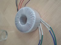
Sure just don't wire them in series. Eg green from one winding to blue on the second winding. That will double the output voltage to 30vAC.
You really need to check the windings with a multimeter and pair them off, label them if you have to with some sticky tape and a marker.
If that wasn't the problem (Wiring it up incorrectly) then there must be a short somewhere in one of the filtering capacitors or somewhere else in the device.
According to this photo the bridge rectifiers are rated for 100v:
http://www.twistedpearaudio.com/images/power/lcbps_kit.jpg
But they are rated for only 2 amps!!
I think you might need to replace the bridge rectifiers and then only use one of the windings. Twisted pair has apparently used a low value BR to keep costs low but it has also prevented the ability to use a 200VA transformer in place of a 100VA one.
I think inrush current killed it.
http://www.vishay.com/docs/88532/3n253.pdf
You have an option you can upgrade the bridge rectifier and that should be the end of it, you can then keep the two windings wired in parallel.
Last edited:
Hi,
Check the the transformer voltage output with a volt meter and compare the voltage with the bridge rating voltage.
I get 16v off both sets of 2nd's when I keep them paired as in my last post.
12.5 and 13v if I mix the 2nd's
This leads me to believe it is important to keep them paired, but, would it cause the rectifiers to blow if they are mixed?
Sure just don't wire them in series. Eg green from one winding to blue on the second winding. That will double the output voltage to 30vAC.
You really need to check the windings with a multimeter and pair them off, label them if you have to with some sticky tape and a marker.
If that wasn't the problem (Wiring it up incorrectly) then there must be a short somewhere in one of the filtering capacitors or somewhere else in the device.
According to this photo the bridge rectifiers are rated for 100v:
http://www.twistedpearaudio.com/images/power/lcbps_kit.jpg
But they are rated for only 2 amps!!
I think you might need to replace the bridge rectifiers and then only use one of the windings. Twisted pair has apparently used a low value BR to keep costs low but it has also prevented the ability to use a 200VA transformer in place of a 100VA one.
I think inrush current killed it.
http://www.vishay.com/docs/88532/3n253.pdf
Thanks! I wondered about that. So my homemade ps where I used the SB160E-G Comchip Technology | Mouser Rectifiers I had the same problem but it worked fine with a 100va. Those are rated at 1amp but max surge current is 30amp. That won't withstand the inrush?
Thanks! I wondered about that. So my homemade ps where I used the SB160E-G Comchip Technology | Mouser Rectifiers I had the same problem but it worked fine with a 100va. Those are rated at 1amp but max surge current is 30amp. That won't withstand the inrush?
Inrush Current
A 500VA transformer can deliver over 100A if the circuit looks like a dead short to it.
And that is what capacitors look like when they are completely discharged. If its for long enough then it may exceed the bridge rectifiers ratings.
AndFigure 3A is two captures combined into one, and shows the inrush current waveform captured when power is applied at both the mains zero crossing point and at the peak. The transformer is a single phase, 200VA E-I type, with a primary resistance of 10.5 Ohms. Absolute worst case current is simply the peak value of the mains voltage (nominally 325V (230V mains) or 170V (120V mains)), divided by the circuit resistance. This includes the transformer winding, cables, switch resistance, and the effective resistance of the mains feed. The latter is usually less than 1 Ohm, and allowing an extra Ohm for other wiring, this transformer could conceivably draw a peak of about 26A.
Things become more complicated when the secondary feeds a rectifier, followed by a large bank of filter capacitors. Worst case inrush current is still limited by the winding (and other) resistances, but the capacitor bank appears to be a short circuit at the output of the transformer. Depending on the size of the capacitors, the apparent short circuit may last for some time. During this period, the transformer will be grossly overloaded, but this is of little consequence. Transformers can withstand huge overloads for a short period with no damage, and they will normally last (almost) forever even when subjected to such abuse many times a day.
So there are two ways you can go about this, you can install a soft start circuit which sits on the mains side and prevents the transformer from giving massive amounts of amperage to the (temporarily) shorted capacitors and instead charges the capacitors slowly.
Or you can upgrade the bridge rectifier.
Its up to Twisted Pear to tell you wether or not its a good idea to do this.
I would just go back to having a 100VA winding.
Last edited:
Inrush Current
A 500VA transformer can deliver over 100A if the circuit looks like a dead short to it.
And that is what capacitors look like when they are completely discharged. If its for long enough then it may exceed the bridge rectifiers ratings.
Ok, Thanks so much Freax! I get it now, I'm going to upgrade all the rectifiers.
Ok, Thanks so much Freax! I get it now, I'm going to upgrade all the rectifiers.
Just be careful, you did say earlier that the traces on the PCB were nearly burnt off because of this. Check the capacitors for shorts. (Charge them with a battery and measure it with a voltmeter, if the voltage drops quickly or it doesn't hold a charge at all then you have a shorted capacitor.) And... install a fuse onto the secondary winding.
As I said in the previous post (edited) I would just go back to having a 100VA winding.
The traces on the PCB may not be up to handling more inrush current, basically you've reached the limits of the circuit.
Don't say you weren't warned! 🙂
Last edited:
Just be careful, you did say earlier that the traces on the PCB were nearly burnt off because of this. Check the capacitors for shorts. And... install a fuse onto the secondary winding.
As I said in the previous post (edited) I would just go back to having a 100VA winding.
The traces on the PCB may not be up to handling more inrush current.
Don't say you weren't warned! 🙂
Got it! I think I'll start fresh. None of this stuff is costly enough to risk safety, it's going in the trash.😀
Thanks again man!
Hi,
I checked your transformer specs. and it is 200VA 2x15 = 15 volts 6.6 amps. Your bridge it is rating for 1 amp. I will used at least a 6 amps bridge. Since the transformer it is capable to put out a healthy 6 amp out.
I checked your transformer specs. and it is 200VA 2x15 = 15 volts 6.6 amps. Your bridge it is rating for 1 amp. I will used at least a 6 amps bridge. Since the transformer it is capable to put out a healthy 6 amp out.
The bridge is rated for 2A, not to "save money," but because the supply is rated for 1A output (LM317).
The inrush theory is completely wrong. The Ifsm of the bridge is 60A, which is more than enough to handle the tiny inrush of the caps on the supply board.
You have something wrong with your supply, or the circuit you are trying to power with it.
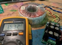
I have a LCDPS being powered happily by a 160VA (22+22V) transformer on my bench right now as a test. The bridges are not even warm. I will post a picture in a moment.
The inrush theory is completely wrong. The Ifsm of the bridge is 60A, which is more than enough to handle the tiny inrush of the caps on the supply board.
You have something wrong with your supply, or the circuit you are trying to power with it.
I have a LCDPS being powered happily by a 160VA (22+22V) transformer on my bench right now as a test. The bridges are not even warm. I will post a picture in a moment.
Attachments
Last edited:
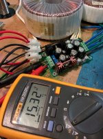
And here it is with 400VA (22+22V) transformer...
Thanks for responding Brian. I'm not sure how to figure out what I did wrong.
The supply worked fine with a different transformer a year ago. I hooked the new antek slightly different than in your pic. See attached pic.
After I smoked that I attached the transformer to a similar circuit that I had built and it did the same thing.
Attachments

Hi,
Check for a short by Removing the transformer wires and check the input resistance at the connector to see if you have short in the circuit. If you remove the bridge then check the resistance at the filter capacitors.
Check for a short by Removing the transformer wires and check the input resistance at the connector to see if you have short in the circuit. If you remove the bridge then check the resistance at the filter capacitors.
Hi,
Check for a short by Removing the transformer wires and check the input resistance at the connector to see if you have short in the circuit. If you remove the bridge then check the resistance at the filter capacitors.
I really don't believe anything was wrong with the Twisted Pear supply. It worked fine a year ago before I unhooked it and put it in a drawer.
I believe either I'm at fault or the transformer. Just not sure what to do. Don't want to keep blowing things up🙁
Capacitors age, dust builds up, solder joints crack...
I would remove/replace the dead bridge and measure the resistance at the inputs (as mentioned above), across the caps, and at the output terminals.
I would remove/replace the dead bridge and measure the resistance at the inputs (as mentioned above), across the caps, and at the output terminals.
Hi,
Check for a short by Removing the transformer wires and check the input resistance at the connector to see if you have short in the circuit. If you remove the bridge then check the resistance at the filter capacitors.
I'm pretty new to all this, can you give me any tips on checking this stuff and what I should see on the meter.
I do have a decent Fluke multimeter.
Thanks guys for all the help!
- Status
- Not open for further replies.
- Home
- More Vendors...
- Twisted Pear
- Smoking Bridges