Ah yes, I forget connector. It is one of the most annoying thing about SMD. One carelessness unplug of cable and crack, the connector is out and the SMD solder pad is gone, then we can throw away an expensive 8-layer board.
So we have to pay attention at what we're doing, so a bit more won't do much harm I guess.
I'm considering SMT for several reasons:
Most of the companies are not manufacturing TH components anymore, so finding good components in that style is getting harder every day.
I don't want to start a new design and when I finish it, in the process of getting the necessary parts, they are not available anymore.
I don't want to get stuck to the past, TH components are simple to solder, they go way back to my youth, but one needs to accept that the world moves on and technology is always evolving.
Space: SMT parts are way more tiny and consume so much less space on the pcb and can be mounted on both sides, something I think would be way more difficult to accomplish using TH.
So that's why I'm considering SMT
After reading all the responses, I got a couple of questions, earlier someone said that he does not like SMT for class A/B designs, or at least that's what I think he meant. Is it because of the inherent thermal effects? Because SMT components have less DP and are less robust?
I'm planning a class AB discrete design with full SMT components, is that a bad idea?
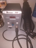
And I got this laying around (for almost 4 years) on my work bench, how bad is it for the job?
I'm considering SMT for several reasons:
Most of the companies are not manufacturing TH components anymore, so finding good components in that style is getting harder every day.
I don't want to start a new design and when I finish it, in the process of getting the necessary parts, they are not available anymore.
I don't want to get stuck to the past, TH components are simple to solder, they go way back to my youth, but one needs to accept that the world moves on and technology is always evolving.
Space: SMT parts are way more tiny and consume so much less space on the pcb and can be mounted on both sides, something I think would be way more difficult to accomplish using TH.
So that's why I'm considering SMT
After reading all the responses, I got a couple of questions, earlier someone said that he does not like SMT for class A/B designs, or at least that's what I think he meant. Is it because of the inherent thermal effects? Because SMT components have less DP and are less robust?
I'm planning a class AB discrete design with full SMT components, is that a bad idea?
And I got this laying around (for almost 4 years) on my work bench, how bad is it for the job?
Attachments
Very few components are designed for that narrow of a market. Nothing prevents you from using a 2SC2240 to drive an LED for example even if it is an "audio power amp transistor".I'm reviving this thread, don't know if you guys after 10 years are still here, but wanted to know if your opinions on SMT vs TH are still the same.
My only concerns about SMT components is about how they are (or not) designed to work for Audio Power Amps.
SMD parts makes automated assembly possible -> lower cost. It also makes smaller gadgets possible. I do see a few PTH boards at my assembly house from time to time, but those are legacy designs used in an industry (oil & gas, military) that doesn't care about production cost but would care about the cost of redesigning the products.
The new and exciting parts are all surface mounted. That's great for the world at large but not so great for the hobbyists. A few years ago I wrote quite a bit on why I no longer support DIY SMD builds. You can find it here: https://www.diyaudio.com/community/threads/modulus-86-build-thread.267802/page-229#post-5738981 That said, the more hardcore hobbyists can certainly build SMD projects without much fuss. I use a solder paste stencil from OSH Stencils, solder paste, and a B&D toaster oven for DIY solder reflow. Just don't use the toaster oven for food after...
These days it seems like some of the larger SMD packages are falling out of favour. At least I seem to notice that 0805 resistors are less available than 0603. That could just be supply chain issues, but it wouldn't surprise me if 0805 and maybe even 0603 are going away. 1206 might get to stick around for power resistors.
As far as the performance of SMD vs PTH parts go, I'd say that if there is a difference between the two, it's more likely that the SMD parts will perform better. That's simply due to their lower parasitic components. But note that not all components are created equal. For example, a physically larger X7R ceramic capacitor will generally have a lower voltage coefficient, thus, perform better than a smaller X7R capacitor. You can find this information in the data sheets and models of the components.
Also note that some garbage ceramics refuse to die. Why anyone would use a Y5V dielectric these days is beyond me (ok, fine! it's because of cost, DUH!) but you can still buy them. Those "capacitors" honestly make better temperature sensors than capacitors and they're not very good temperature sensors either. 🙂 But if you buy a good C0G/NP0 dielectric capacitor (PTH or SMD) you get something that's pretty close to an ideal capacitor that will outperform a PTH film capacitor in many cases.
Same for resistors. If you buy thick film or some thin film types you're asking for trouble. A "film" SMD resistor is basically a substrate with two end caps and some conductive paint applied to it. If you want good audio performance get a metal film resistor. The Susumu RG-series is excellent, for example. I have yet to measure any difference in performance between a PTH metal film resistor and an SMD metal film resistor. NiChrome is NiChrome... Or TiW or whatever metal film is used. Do watch the power rating if you use them in a power amp, though. Or the voltage rating if you use them in tube circuitry.
Tom
Thin film is metal film! And yes a larger thin film SMT resistor will perform better than a tiny one. Thick film is Ruthenium oxide particles fired in glass (ie a metal oxide resistor) - you can call that conductive paint I suppose, but its more sensitive to cracking than paint would be...
Ceramic capacitors for logic decoupling don't have to have any performance, the capacitance can vary of an order of magnitude, it can be leaky, microphonic, doesn't matter one jot, so long as it swallows current edges without generating voltage edges...
Ceramic capacitors for logic decoupling don't have to have any performance, the capacitance can vary of an order of magnitude, it can be leaky, microphonic, doesn't matter one jot, so long as it swallows current edges without generating voltage edges...
Mmmmmaybe.... Some types still seem to have a higher voltage coefficient than others. That's problematic if you want low distortion and have significant signal across the resistor - as you would in the feedback resistor of a power amp.Thin film is metal film!
In which way? My example was for capacitors.And yes a larger thin film SMT resistor will perform better than a tiny one.
Yeah. I was being a bit nonchalant in my description. Either way thick film is fine as the series resistor for an LED but not so hot in (most) audio applications.Thick film is Ruthenium oxide particles fired in glass (ie a metal oxide resistor) - you can call that conductive paint I suppose, but its more sensitive to cracking than paint would be...
Tom
Yes, but there are hybrid approaches - parts with metal pegs that go partway through a plated hole to greatly increase the strength of the surface mounting bond, but with the tolerance slack enough between peg and hole that the part can be pick-and-placed by ordinary SMT P&P machine. Many micro USB sockets are like this for instance.Ah yes, I forget connector. It is one of the most annoying thing about SMD. One carelessness unplug of cable and crack, the connector is out and the SMD solder pad is gone, then we can throw away an expensive 8-layer board.

Consider the melf package as a precision smd resistor. I used them for the first time when I built the Samual Groner low noise preamp from a linear audio article
Apart from electrolytic capacitor and class A/AB driver/output device, I prefer SMD part. They are space-efficient both in storage and especially PCB. Soldering and Desoldering SMD part is much more faster and convenient than THT part, and desoldering SMD part is far less likely to damage the PCB t
Would SMD parts make much of a difference on A/AB class? In what way you prefer TH? Is it because of thermal dissipation?
@tavares_costa : it is primary about thermal dissipation. Some TrenchFet in POWERPAK package have thermal dissipation which can rival TH components, but they are good for switching circuit, not linear one like class A/AB.
The other reason is that many components only available in TH package like 2SC4793, 2SC4883, 2SC5171, 2SC3503, KSC1845,... and their counterparts
The other reason is that many components only available in TH package like 2SC4793, 2SC4883, 2SC5171, 2SC3503, KSC1845,... and their counterparts
The MPJA.COM protoboards can accommodate both TH and SMD -- the technique for SMD is to place the solder paste on the holes, place the parts (usually 0805, but also 1206) on adjoining pads and pop into the reflow (mcu controlled toaster oven in my case). I believe that one of our former members said he used a "hot-plate" for prototypes at ADI.
For a run between parts separated by a few holes, I use #28 wire.
A bit of a kluge, but if I am making a proto I will use through-hole IC's and sockets.
For a run between parts separated by a few holes, I use #28 wire.
A bit of a kluge, but if I am making a proto I will use through-hole IC's and sockets.
SMD components are smaller and lighter than through-hole components. This allows for light weight PCBs and higher density parts.
Be careful with Pd as the smt versions like a sot-23 is not the same, it’s lower than a to-92 however there are some versions like sot-223 that have higher Pd than the to-92
In which way? My example was for capacitors.And yes a larger thin film SMT resistor will perform better than a tiny one.
I am aware of two effects:
A larger resistor will have higher thermal to ambient dissipation, but also a higher thermal mass. The former determines steady state power dissipation, the latter is important for pulse power dissipation. Because the thermal relaxation time to ambient is rather large (seconds), most short term energy leads to heating of the resistive element (<1ms regime) as well as the ceramic substrate (~100ms). (I suppose that is the reason that maximum pulsed energy graphs for resistors usually level out at a few hundred µs pulse duration.) As I see it, for audio the thermal heat capacity as well as temperature coefficient of resistance mostly defines thermal related resistor distortion. Thus a physically larger resistor should exhibit lower distortion (all else the same).
The other effect is related to the voltage coefficient of resistance (VCR). A technical article by Stackpole says that at least for high value thick film resistors, larger size resistor will have better VCR because lower ohmic value materials may be used. But I don't know if this also applies to (comparatively) low value thin film resistors. But it seems reasonable to me.
That's my understanding as well. You can make a physically larger resistor by using many resistors in parallel. That's the approach taken by Audio Precision in the APx555.Thus a physically larger resistor should exhibit lower distortion (all else the same).
I don't know exactly what causes the VCR in resistors but it seems reasonable, also to me, that physics would be more in the way with a smaller resistor, and that a physically small resistor would have worse VCR as result.
Tom
MELF are awesome ... except for assembly. You can get the same good results with Susumu RG-series as you can with a MELF as long as the power dissipation is low. MELF do tend to support higher power dissipation as I recall.Consider the melf package as a precision smd resistor.
Tom
Hi Tom
I had no problem hand soldering MELF0207 but I suspect it might be more problematic for a pick n place machine, esp if they are not in a reel and are delivered in bulk. The contract mfr might charge a premium if one specified them, however I have never inquired.
Rick
I had no problem hand soldering MELF0207 but I suspect it might be more problematic for a pick n place machine, esp if they are not in a reel and are delivered in bulk. The contract mfr might charge a premium if one specified them, however I have never inquired.
Rick
If you pulse a resistor over its maximum dissipation you probably should specify a larger resistor? Pulse limits are to do with thermal shock damage I think, not linearity of resistance when used within continous ratings.A larger resistor will have higher thermal to ambient dissipation, but also a higher thermal mass. The former determines steady state power dissipation, the latter is important for pulse power dissipation. Because the thermal relaxation time to ambient is rather large (seconds), most short term energy leads to heating of the resistive element (<1ms regime) as well as the ceramic substrate (~100ms). (I suppose that is the reason that maximum pulsed energy graphs for resistors usually level out at a few hundred µs pulse duration.) As I see it, for audio the thermal heat capacity as well as temperature coefficient of resistance mostly defines thermal related resistor distortion. Thus a physically larger resistor should exhibit lower distortion (all else the same).
The other effect is related to the voltage coefficient of resistance (VCR). A technical article by Stackpole says that at least for high value thick film resistors, larger size resistor will have better VCR because lower ohmic value materials may be used. But I don't know if this also applies to (comparatively) low value thin film resistors. But it seems reasonable to me.
Thermal distortion at audio frequencies is unlikely to be seen if you try to measure it in most audio circuits with standard line level signals. It can be measured in higher power situations, such as a power amp feedback network with very small resistors - best to use larger resistors with a smaller tempco in that situation - 1210 thin-film is my choice usually. If you plot distortion against frequency thermal distortion shows as a rise at low frequencies that appears at higher power (although electrolytic capacitor distortion in coupling caps can also appear similarly)
Metal oxide (thick film) are definitely non-linear, the effect will be exacerbated by smaller devices, but its usually a fairly small effect - it does pay to use thin-film in critical resistors (filter components or feedback-network) as metal is very linear.
Found an interesting article from 1967 about the development of thick-film resistors: https://technology.matthey.com/article/11/4/126-129/
I have one of those. It's for sale!Elektor had a toaster-oven controller a while back -- if you're going to use solder paste, don't use the toaster-oven to make your pizza == you need a separate one for that.
Jan
- Home
- Design & Build
- Parts
- SMD vs through hole