Re Post #1456 and #1459
QUOTE]Originally posted by AndrewT
Hi,
Many commercial amps are quoting -1db @ 4Hz. This implies an input filter set at 2Hz. If the other filters are set in the ratio 1:1.4:2 then the NFB filter will be near 112mS.[/QUOTE]
Andrew,
Is the above you refer to the same as you refer to in Post #3:
http://www.diyaudio.com/forums/showthread.php?postid=760281#post760281
of the "diyAudio Forums > Top >Amplifiers >Solid State >Want to go active, need good 100w per chan amp for 6 spkrs" thread:
http://www.diyaudio.com/forums/showthread.php?threadid=67372
I am still trying to figure out how the input RC and PSU RC are calculated. With more time I suspect I will figure those two out.
Regards,
John L. Males
Willowdale, Ontario
Canada
13 December 2006 16:27
QUOTE]Originally posted by AndrewT
Hi,
Many commercial amps are quoting -1db @ 4Hz. This implies an input filter set at 2Hz. If the other filters are set in the ratio 1:1.4:2 then the NFB filter will be near 112mS.[/QUOTE]
AndrewT said:Hi Key,
surely you've seen other posts from both myself and others quoting the ratio between the input filter, the NFB filter and the PSU filter to ensure the low frequency stability of an amplifier! i.e. avoid motorboating.
Andrew,
Is the above you refer to the same as you refer to in Post #3:
http://www.diyaudio.com/forums/showthread.php?postid=760281#post760281
of the "diyAudio Forums > Top >Amplifiers >Solid State >Want to go active, need good 100w per chan amp for 6 spkrs" thread:
http://www.diyaudio.com/forums/showthread.php?threadid=67372
I am still trying to figure out how the input RC and PSU RC are calculated. With more time I suspect I will figure those two out.
Regards,
John L. Males
Willowdale, Ontario
Canada
13 December 2006 16:27
Hi K,
yes, the same as that old post3.
input high pass RC = Zin * (series DC blocking caps from source & amplifier)
PSU RC = (speaker impedance) * (smoothing capacitance per channel)
yes, the same as that old post3.
input high pass RC = Zin * (series DC blocking caps from source & amplifier)
PSU RC = (speaker impedance) * (smoothing capacitance per channel)
AndrewT said:
input high pass RC = Zin * (series DC blocking caps from source & amplifier)
Andrew,
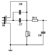
Assuming zero source capacitance for the Leach Amp input (as attached image taken from Jen's schematic) when the signal input is via pins 1/2:
input high pass RC = R17 * (0 + C6||C7)
Regards,
John L. Males
Willowdale, Ontario
Canada
15 December 2006 02:41
Attachments
Hi K,
yes, the 1/2 input matches the formula you posted.
and your source has no DC blocking capacitor?
yes, the 1/2 input matches the formula you posted.
and your source has no DC blocking capacitor?
Hi Andrew,
I assume the other 1/2 I did not post was the PSU, but that was straight forward.
I chose to ask the question without knowing the source C just to make the question simple while at same time letting you know I made that assumption.
I am not sure off had with the three preamps I have off hand what their output C are. I have two SS preamps and one tube - all commercial units. I hope to build a couple preamps myself later, but preamps are not as important as starting with the amps first for my needs. The quick research I had done of pre-amps had as many varied output C as amps input C. Hence for the purpose of the real question at hand I noted I would assume the source C to be Zero.
I do have a variation on the input RC calculation due to the different input configurations. One of those variations is where the R17 like resistor is on the same side of as C8 like capacitor. With R11 like resistor between C6||C7 like capacitor(s) and C8 would R11 need to be factored into the input RC calculation? If so, how would the equation need to be adjusted?
Regards,
John L. Males
Willowdale, Ontario
Canada
15 December 2006 05:23
Hi K,
I understand the logic in keeping the question simple. There are times I wish I could emulate that.
Let's take an example, and again I shall try to keep it simple and assume there are no intervening caps nor resistors between the pre output and the Leach input. This allows simple single pole analysis.
Leach input is 2u2Fand 22k giving RC=48.4mS and F-3db=3.3Hz, when fed from Rs=0ohm
Add in 1uF to the Rs and the effective series capacitance becomes 0.69uF changing the RC to 15mS and F-3db to 10.5Hz.
keypunch said:I do have a variation on the input RC calculation due to the different input configurations. One of those variations is where the R17 like resistor is on the same side of as C8 like capacitor. With R11 like resistor between C6||C7 like capacitor(s) and C8 would R11 need to be factored into the input RC calculation? If so, how would the equation need to be adjusted?
Hi Andrew,
Thanks for your reply. I am not sure if you missed the follow up question with an alternate input configuration.
As to being short and to point, I bet you find it scarey I can be. lol lol lol lol Not to mention others that have seen my postings. Suffice to say often I choose to ask many question at once rather than via several postings broken up. Sometimes because they are related, other times as they were all on my mind so I asked before I forgot to ask, let alone run risk of forgetting the other questions. The questions are less now as I know a bit more thanks to people like you.
Regards,
John L. Males
Willowdale, Ontario
Canada
15 December 2006 16:54
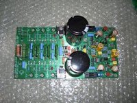
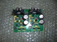
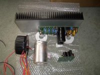
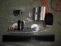
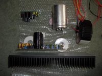
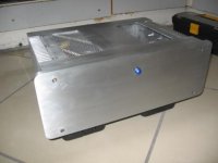
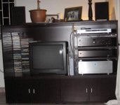
Hi all of you. Here are some pictures of where I am up to, (Yes I know I am way behind some of you) but getting parts etc is just a mission I under estimated when I started this.
Anyway the pictures show how I intend to lay out one channel and the other is mirrored on the other side. I was trying to get the input as close to the chassis and as short a run as possible and the transformer, rectifier and caps as far away. (within the cabinet of course)
I haven't bought the bridge rectifiers yet so any recomendations will be welcome.
Perhaps some of you mite like to post some more pictures of the completed amp and feild any comments on how it is sounding etc.
One last thing is that I have read most of the posts (some of which are just going over my head technically) but can we still confirm that the amp will work fine as designed by Jen's etc.
I would hate to have gone through this whole exercise to find out it wasn't going to be up to my expectations.
Regards Ian
Attachments
Loboone said:I haven't bought the bridge rectifiers yet so any recomendations will be welcome.
Perhaps some of you mite like to post some more pictures of the completed amp and feild any comments on how it is sounding etc.
One last thing is that I have read most of the posts (some of which are just going over my head technically) but can we still confirm that the amp will work fine as designed by Jen's etc.
I would hate to have gone through this whole exercise to find out it wasn't going to be up to my expectations.
Regards Ian
Ian,
I have no direct experience with rectifiers as yet, but have done a fair bit of reading about them. You find two basic camps fast and normal speed and to or not to place small caps across the rectifier terminals to dampen diode ringing. My suggestion to you is to buy quality rectifiers and build a good basic PSU. It would be good to buy a rectifier if at least 600 PIV and 35 amps if you are using one rectifier to supply both sides of the rail and two modules. Also buy a rectifier that has the lugs and metal case or plate that allows you to mount the rectifier to the chasis. Chassis mount acts as heatsink for the rectifier. Although normally the rectifier will not get warm, it is costs no more and give one more level of thermal safety in the whole project "food chain" and for the possible odd exception the rectifier would heat up if it was not thermally mounted. The key is amps rating as the capacitors can strain the rectifier on start up even with a 300VA transformer. If you use a torid that adds additional strain to the rectifier evan at 300VA. Many say you need to use a start start circuit for 300VA and above. Personally I think you may need a soft start before 300VA depending on the amount of capactance in the PSU.
I am focused on a MOSFET design as most of the transistor devices for the BiPolar designs I cannot purchase locally. Obviously I will not have any pics to post.
Jens does solid design work. That said the Leach Amplifier is a proven design. Jens made great effort to update the design in terms of moden parts available. Even Professor Leach has postedf on his site alternate parts as the design age has resulted in many of the original design parts not being available or very hard or expensive to obtain. This means you are building a proven design. A design I would build as so well proven and the unsurpassed quality of Jen's PCB and design skills. You have a set of Jen's PCBs. The time, effort and quality of the board Jen's creates is one example of ensureiong your success, but the dedication of Jens. Also Jens built a 6 or seven channel HT like amplifier of this design. So rest assure you are building one excellent design with PCBs that are hard to surpass in quality and design though/experience.
As to expectactions, only you know what your expectations are. You seem to be enlightened and take the time to read the thread which is excellent and can help be aware of any important tips or experiences of others building this version of the Leach Amplifier. You mentioned some of the inforamtion was technically over your head. That is ok, just be sure you understadn what you need to to allow you o complete the build. Like a car you do not need to udnerstand all the engineering, theory and sceince to select, test and decide on a car. The same applies to the amplifiers you are building. You do not need to understand for example all the ins/outs of the PCB design and decisions made. You are doing a careful and excellent job populating and sodering the parts to the board. Clearly the extra effort you have experienced in sourcing the parts. That happens to many of us. Just be sure you are clear on all the options and their importance for you in building the project. Be very aware of the preflight tests and how you are to set up the modules. Wear safety glasses and a face shield while you work on the amp as even a small innocent device can blow right into your eye. Such cases are rare, but can happen and not be due to your assemply and preflight checking missing something. Devices can be defective and thereby cause that part or related to defective part to fail.
Lastly, just be aware you may need to play the amps for a few weeks or couple months for them to "settle in". There are many on both sides of this burn in tiem camp. Suffice to say some parts may need initial curing and depending on the type and make/model of part may take some time. PErsonally I think I have experienced this "settle in" time. Just be aware you may swear the amp is changing quality over time and may even bounce about wildly for while until it settles in. Again there is a very passionate camp on both side of this matter. I do not wish to open up a discussion about this on this thread. There are threads here that discuss this specifically where you can do more reading later to understand why this may be or why it cannot be.
Keep doing things as carefullly and with reading the thread and maybe making some copy/paste notes in file that are important in your mind. If you do nto udnerstand something then ask. I am sure what you would ask is more to allow you to complete the project and not to understand the deep theory behind. There are people here that can explain to the level you need and in a manner you need to be able to understand. I am sure you will end up with amplifiers you will enjoy your interst in music such that the amplifier is not noticed in the music you play.
Regards,
John L. Males
Willowdale, Ontario
Canada
16 December 2006 04:55
missed that one.keypunch said:I do have a variation on the input RC calculation due to the different input configurations. One of those variations is where the R17 like resistor is on the same side of as C8 like capacitor. With R11 like resistor between C6||C7 like capacitor(s) and C8 would R11 need to be factored into the input RC calculation? If so, how would the equation need to be adjusted?
The two alternatives do require different analysis.
The Jen's/Leach version loads up the LTP bases differently.
I prefer your alternative simply because it puts almost exactly the same loading on the two sides of the LTP, thus ensuring balance. The alternative also gives slightly less gain since the resistor ladder removes the +1 from the gain equation Rnfb/Rlower +1 giving just Rnfb/Rlower.
The input impedance of Leach/Jens is R17//[R11+C8], whereas alternative Zin = R11 + [R17//C8] and the R11 + R17 is inserted into the filter equation.
the rectifier needs to be just over three times the AC voltage of the transformer. 60-0-60Vac can use a 200PIV rectifier. You only need to go to 400PIV if you are over 60-0-60Vac. There is a small disadvantage in using an overated PIV when it is not needed.keypunch said:rectifier if at least 600 PIV and 35 amps................ If you use a toroid that adds additional strain to the rectifier even at 300VA.
The toroid does not cause additional stress on the rectifier.
The rectifier has to pass the peak currents into the smoothing caps. At switch on, this current is extremely large and falls quickly to nearer operating levels over a period of half to a couple of seconds.
There is an additional stress on the primary side cabling and fuses from using a toroid due to the need to build up a magnetic field that is worse than using EI transformers. Although I have never seen this stated this extra field building current may delay and/or reduce the initial peak secondary output current.
The result may be that the toroid is kinder to the smoothing caps and rectifier not worse.

Hi,
a christmas present to you all.
from the resurrected BOAK thread.
a christmas present to you all.
from the resurrected BOAK thread.
any feedback from those that have added regs to Jens' board?In case you have not built the PS yet. Here are some comments.
In 1982 I added a Boak/Jung regulator to my Leach Low TIM power amps I had built. This amp was compared to another Leach that had 500VA toroids. Mine had a 350 VA standard transformer and the RS boost transformers that the articles used. The other amp was of superior build quality and also used flat copper conductors like some are using today. All amps were monoblocks or dual monos.
The difference in the amps was immediate and not at all subtle. The bass was more dynamic and solid, giving the sense that there was unlimited power. It seemed as though we had gotten new speakers and if anything the article is conservative in what was to be expected. The soundstage was also more three dimensional and open.
Will it do it in your amp. Don't know. We listened to a similarly modified ST150 and it was not even close to the sound of the Leaches. Maybe the Leach amp was better.
My friend immediately added regulators to his as well. However, he also doubted what should have been of little benefit and modifed another of his Leach's front end by cascoding. The regulated amp still sounded better by a long shot.
It is not a cheap option. My friend also took the time to design a board that combined the boak regulator with Jung's preregulator. These were used in all of my amps.
Alternatives for Transistors in the 6 Trans Version
Hi,
I am about to build the smaller version, but I have problems to find the trans in the partslist?
The Toshiba 2SA1302/2SC3281 are out of production since 2000 (according to Toshiba) - today most parts are "fakes" or "cheap versions" built in License in chinese factories with worse performance.
Can I use the replacement versions: 2SA1943 and 2SC5200 in the 6 Trans smaller leach amp design?
Or are the MJL1302/MJL3281 better?
Can someone help me with this.....I am new to DIY amps 🙂
Hi,
the 1943/5200 are a good equivalent at lower voltages.
But they have a poor SOAR at higher voltages.
I recommend using +-50Vdc for three pair into 4ohm speakers.
This can be got with a 35-0-35Vac centre tapped transformer.
If you have only 8ohm speakers and will never use 6ohm or 4 to 8ohm, then the Leach recommnedation of 40-0-40Vac giving +-58Vdc should be OK, but not for heavy duty work.
Keep in mind that the two pair of To3 devices are a lot more robust than three pair of these plastic devices.
A few component values need to be scaled for the lower voltage.
An alternative is three pair of MJL4302/4281 which have 53% more dissipation and better SOA, 1.85times more current @ 60Vce. Direct from ONsemi guarantees no fakes.
- Status
- Not open for further replies.
- Home
- Amplifiers
- Solid State
- Smaller Leach Amp V1