probably two zeners with cathodes connected
before you do anything, make sure Lazy Cat haven't made any changes
first one was brought alive just a few days ago
before you do anything, make sure Lazy Cat haven't made any changes
first one was brought alive just a few days ago
Might be an odd symbol for Zeners .
Series opposite connected in this case.
*If* you had posted the rest of the schematic, function would clear the doubt, so please do it now.
Series opposite connected in this case.
*If* you had posted the rest of the schematic, function would clear the doubt, so please do it now.
Class A is not a guarantee of low distorsion wich is dependant
of the amp global linearity.
Class A eliminates (not _mitigates_ like feedback in ab) the major source of distortion
in a power amplifier: crossover distortion.
@Renioo
Have a look at Andrew C. Russells(Member Bonsai here on diyaudio.com) new amplifier:
Ovation sx-Amplifier
excellent execution and documentation. Very recommended.
He has A/B amps too.
I liked Hiraga's amp very much
if 10-15watt is all you need...then its really sweet, absolutely
now I think of it, I used mine to drive Apogee diy clones
funny, but it worked quite well, while other 'normal' speakers didn't
if 10-15watt is all you need...then its really sweet, absolutely
now I think of it, I used mine to drive Apogee diy clones
funny, but it worked quite well, while other 'normal' speakers didn't
http://zapodaj.net/9e94a9cb7ad86.jpg.html
It's the one to which Lazy Cat refers in first post of VSSA
I'm ready to change mind because I can't get those mosfets and other without ordering from few shops at once.
It's the one to which Lazy Cat refers in first post of VSSA
I'm ready to change mind because I can't get those mosfets and other without ordering from few shops at once.
Last edited:
Whatever, I ordered Fet's and stuff, only capacitors and resistors are left, but that's not a problem. If I get it right, all resistors not marked are 0.5W?
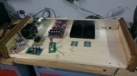
Took long time, but finally VSSA is at home and everything is clear... I need to think about arrangement.
An externally hosted image should be here but it was not working when we last tested it.
Something about this does not seem right... not saying it won't work, but the combination of parts does not seem to make complete sense.Looks like this
If the transformer is +/-35V AC, that translates to ~45V DC rails. The VSSA boards from LC's group buy are +/-40V maximum (the breakdown voltage of the Jfet on the board is 40).
The maximum pk voltage out at 45V rail will be about 33Vpk, ~23V rms, which would be around 65 watt per channel into 8 ohms. If that is the case, the heatsinks shown in the pic seem too small.
At a guess, you would need a heatsink rated for around 0.4 degrees C/watt, or forced air cooling (a fan).

The heatsinks will have a 92mm fans on back, so it propably would eliminate the problem in a bigger part
Well, at least ask someone in the VSSA thread about the supply voltage then... not sure how close to 40V you have to keep.The heatsinks will have a 92mm fans on back, so it propably would eliminate the problem in a bigger part
Supply voltage is 20-45V. Still I think about dropping the voltage, but it's a bit troublemaking with such a power. Maybe you have an idea?
Why such a large range?Supply voltage is 20-45V...
First I would ask someone if you can use that voltage as is.
You can regulate anything, but like you said, it is a lot of extra complexity. 🙁
There's a way of simply unwinding the trafo, but I will have to look. There is a possibility of switching it from 110-120 to 220-230 and it also has a small 24v output. I will have a look.
I would ask in the Power Supply forum, someone else probably has an answer.There's a way of simply unwinding the trafo, but I will have to look. There is a possibility of switching it from 110-120 to 220-230 and it also has a small 24v output. I will have a look.
Unwinding the kind of transformer in your pic, is not as easy as it may look.
I would say,
1) find out how important the max voltage is - people who read the VSSA thread have been following that design for a long time, someone will know that answer.
2) There are pass transistor regulators that use only a few parts, and can be wired point to point. If you only need to drop a few volts, that is the simplest solution (I think).
3) Lazy Cat is recommending a switching power supply, which is expensive, but, there may be much cheaper alternatives, IF you only need a moderate amount of power, as you said.
A 75-100 watt +/- 22~25V DC output switching supply would give you plenty of power for single room listening. I seriously doubt I would ever use more, as long as my VSSA is connected to a conventional pair of speakers... 😉
Yea i opened the trafo shield and it's not that easy. I would go on with work on amplifier and try to find something for PSU. I have a lot of space so I can leave it untouched
Lower power is OK with me, still I have problem with choosing proper switching supply. I mean I don't even know how to judge them by quality 😀
- Status
- Not open for further replies.
- Home
- Amplifiers
- Solid State
- Small Amp, Renioo Project