wish me luck guys probably tomorrow I will tested 🙂 a few more parts to install
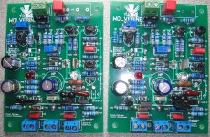
OK , Vargas. I want you to "feel the precision" of the Wolverine.
A few things to consider -
- If you have the "OPT3" jumper bridged , you don't need D7-8.
D7/8 were if you wanted a different Tc for the CCS. I found
perfect Tc on my wolverine without the diodes.
-You don't need D6 if you are using "OPT2"
Edit - if you want to use D6 , you don't need the opt2 Q and R.
- R23 (150R) will equal 4.6ma VAS I , the new standard is 5.4ma.
R23 = 120R will get you that 5.4ma.
- R5 needs to be 100R if you are using "OPT3".
Make sure you have the "A" side of "OPT1" bridged (middle pad/a pad).
OPT 1 chooses between a CCS or earth reference for the input
cascode.
Sorry for the confusion , but I thought all the wolverines were gone.
If there is a demand , I will update the PCB to have fewer options.
Wolverine can be configured in about 6 different ways with the current
PCB.
OS
Last edited:
OK , Vargas. I want you to "feel the precision" of the Wolverine.
A few things to consider -
- If you have the "OPT3" jumper bridged , you don't need D7-8.
D7/8 were if you wanted a different Tc for the CCS. I found
perfect Tc on my wolverine without the diodes.
-You don't need D6 if you are using "OPT2"
Edit - if you want to use D6 , you don't need the opt2 Q and R.
- R23 (150R) will equal 4.6ma VAS I , the new standard is 5.4ma.
R23 = 120R will get you that 5.4ma.
- R5 needs to be 100R if you are using "OPT3".
Make sure you have the "A" side of "OPT1" bridged (middle pad/a pad).
OPT 1 chooses between a CCS or earth reference for the input
cascode.
Sorry for the confusion , but I thought all the wolverines were gone.
If there is a demand , I will update the PCB to have fewer options.
Wolverine can be configured in about 6 different ways with the current
PCB.
OS
ok 🙂 so I have to remove D7 & D8 , R5 now is 100R because I chose OPT3, I will keep D6 and I will remove opt2 Q and R
R23 I’m gonna updated to 120R, “OPTI” 1 side A is already selected, let me know when you get a chance if this is correct before I pick up iron
yes great idea OS to make the Wolverine a bit more simple I was kind was confuse a bit and I think this time I got it thank for explain a lot better OS

Best Regards
Juan
Attachments
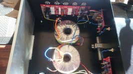
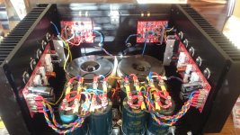
Do you guys think it's ok to install the transformers like this or is it too close to the inductors?
I had the similar enclosure and same issue in fitting two power transformer, and got away with a deck to raise the transformers and create a "basement" space underneath the deck for all the soft-start and monitor circuitry. The transformers in this dual-mono build are of 600VA capacity and they take almost all the 12" available interior depth of the chassis. Just thought it could be an option for you.
Very late to this party and I'm still reading but when I read post 1222
I had to ask why the longer traces of the discreet implementation result in so much better performance? Also, I've read the impressive ppm numbers of the Symasui, the Spooky and the blameless Wolverine but are those THD numbers maximum across the whole bandwidth? Has anyone done a harmonic profile analysis and if so, will someone please point me to it? Ditto for IMD (19+20kHz) distortion numbers. What about gain margin and phase margin analysis? I know these builds are supposed to be stable under load but some tests of the PM and GM would be nice to see. The only information I lack after the questions above have been addressed are the BOM or project budgets for the builds above. Thanks in advance to ostripper, Canadian Jason and all the other contributors here for making this happen.ostripper said:PS - the "symasui" is a HUGE ne5532 IC , and the "blameless" (wolverine)
is a HUGE TL071/72 IC ..... same circuits !!!
Last edited:
Do you guys think it's ok to install the transformers like this or is it too close to the inductors?
Could you stack the transformers? Looks like the case is tall enough.
I think is good idea to stack them up I have seen that before, it will give more space for the capacitor bank 🙂
Looks like both transformers could be mounted to the front plate. Aluminum would act as a heat sink. This leaves most of the chassis bottom for capacitors and protection circuits/relays.
Is there a pdf available for etching a single pair OP? I think I would like to build one with a pair of Sanken MT200. Thanks!!!
Thanks, found it!!!
Very late to this party and I'm still reading but when I read post 1222I had to ask why the longer traces of the discreet implementation result in so much better performance? Also, I've read the impressive ppm numbers of the Symasui, the Spooky and the blameless Wolverine but are those THD numbers maximum across the whole bandwidth? Has anyone done a harmonic profile analysis and if so, will someone please point me to it? Ditto for IMD (19+20kHz) distortion numbers. What about gain margin and phase margin analysis? I know these builds are supposed to be stable under load but some tests of the PM and GM would be nice to see. The only information I lack after the questions above have been addressed are the BOM or project budgets for the builds above. Thanks in advance to ostripper, Canadian Jason and all the other contributors here for making this happen.
Why do they exceed the IC's ?
-Better silicon in individual discrete's plus TMC compensation for the wolverine
and cascodes for the symasui.
-The IC's (P-N)matching is better out of the box , but these discrete's have
blocking caps or a full servo to even things out.
-These circuits swing >100V p-p , op-amps just a few volts. The higher
output relative to the noise of the silicon is greater by a large factor.
- In general , these circuits are "embellished" compared to their IC
equivalents .... much lower THD would be expected here.
Member thimios had done scope and FFT's of the real amps in this thread.
I'm not sure about IMD , but similar designs (Vzaichenko / astx) show
very good results.
OS
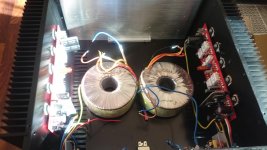
I ended up mounting them like this to get good weight distribution and short cables for the psu. If the inductors pick up noise, I can stack them in the middle.
88Kuf per channel .. wow! Ultra low ripple for sure.
And roomy 5U heatsinks - you should have <35C operation 100ma bias or
30C @ 60ma bias.
Wait till you hear effortless 1/2kw peaks out of it - hope your speakers
are up to it !
OS
They actually measured 25kuF each with my Esr meter, so it's 100kuF per channel 🙂 looking forward to listen to the monster. I'm gonna use it on some Klipsch RP280 so there should be plenty of headroom.
Damn it OS! I just bought Spooky boards and you now have CHANGED the design. I've waited thirty or so years since I built the Leach amps and now rebuilding the chassis with the spooky. I sure hope this change really makes a damn difference! G.R.H.
Damn it OS! I just bought Spooky boards and you now have CHANGED the design. I've waited thirty or so years since I built the Leach amps and now rebuilding the chassis with the spooky. I sure hope this change really makes a damn difference! G.R.H.
The beauty of the Slewmaster series is that the IPS boards can be easily swapped out for another. I wouldn't worry though. The original Spooky is beautiful.
Hello Terry
greetings i want to make the orignal spooky amp is it possible to share
the schematic and pcb layout the one you have tested if possible
warm regards
Andrew
greetings i want to make the orignal spooky amp is it possible to share
the schematic and pcb layout the one you have tested if possible
warm regards
Andrew
- Home
- Amplifiers
- Solid State
- Slewmaster - CFA vs. VFA "Rumble"