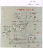
To my testing board,it is necessary to trim CCS for 5mA(hot tran.) LTP current in order to take 1V1 on R23,R30Lowering R23-R30 will increase VAS current. The 1K ohm resistors in the Two LTP/paired with the IPS current defines the VBE of the VAS, the combined VAS railresistors the nby ohms law defines the VAS currents.
Last edited:
To my testing board,it is necessary to trim CCS for 5mA(hot tran.) LTP current in order to take 1V1 on R23,R30
OK , R4/5 and 21/22 = 1.5K . Here , we can reduce input pair I greatly
without affecting gain.
Simulated 2.7ma R15/16 current to get that 11ma at VAS (5.5ma output).
A trimmer setting (500R trimmer) of about 180-200 ohms will get this
reading.
OS
Hi Pete,
What value are you using in the emitters in that simulation? I have 68R and Thimios has 47R.
Thanks, Terry
What value are you using in the emitters in that simulation? I have 68R and Thimios has 47R.
Thanks, Terry
Is this ok?.OK , R4/5 and 21/22 = 1.5K . Here , we can reduce input pair I greatly
without affecting gain.
Simulated 2.7ma R15/16 current to get that 11ma at VAS (5.5ma output).
A trimmer setting (500R trimmer) of about 180-200 ohms will get this
reading.
OS
Attachments
47 Re all around , and those 1.5K's.
Thimios's representation is ideal. I overlooked the fact that this
simple amp is NOT cascoded. Input pairs see full rails , better to
run closer to 1ma.
Spook could run 3ma each , as the 4 input semi's are cascoded to
only 12V.
I wanted to keep symetri' real simple.🙂
OS
Thimios's representation is ideal. I overlooked the fact that this
simple amp is NOT cascoded. Input pairs see full rails , better to
run closer to 1ma.
Spook could run 3ma each , as the 4 input semi's are cascoded to
only 12V.
I wanted to keep symetri' real simple.🙂
OS
Here are new measurements.47 Re all around , and those 1.5K's.
Thimios's representation is ideal. I overlooked the fact that this
simple amp is NOT cascoded. Input pairs see full rails , better to
run closer to 1ma.
Spook could run 3ma each , as the 4 input semi's are cascoded to
only 12V.
I wanted to keep symetri' real simple.🙂
OS
Attachments

Last edited:
Here are new measurements.
You notice offset is ideal for a non-servo'ed amp ! Did you adjust
the CCS to get there ?
Symetri does have better offset natively. Q7/9 are a hard shunt to ground.
DC NFB "forces" the VAS to zero. Better than a standard "leach".
Also , is everything real cool at 1ma ? Changing these values .... still
20ppm/ 20K/ 50W/ 8R. A superb "entry level" slewmaster IPS.
OS
.... A superb "entry level" slewmaster IPS.
Pete,
Why do you call this an entry level IPS? It looks to be a great performer or am I missing something?
Did you adjustYou notice offset is ideal for a non-servo'ed amp ! Did you adjust
the CCS to get there ?
Symetri does have better offset natively. Q7/9 are a hard shunt to ground.
DC NFB "forces" the VAS to zero. Better than a standard "leach".
Also , is everything real cool at 1ma ? Changing these values .... still
20ppm/ 20K/ 50W/ 8R. A superb "entry level" slewmaster IPS.
OS
the CCS to get there ?
Yes i did.It is possible to go down offset to 0mV but for lower VAS current(about 800mV/100R=8mA.)
LTP current is 2mA not 1mA😕
Ok i see now, you mean 2mA/pair = 1mA for each transistor.
Last edited:
Pete,
Why do you call this an entry level IPS? It looks to be a great performer or am I missing something?
Entry level = easier to build than a Badger/blameless.
Edit - A new builder should start with a symetri !
No denigration of performance intended. It actually has advantages
over the blameless (overload for one).
OS
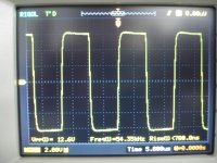
symetri long test
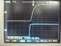
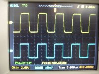
Here are details.
Yellow=output signal
blue=input signal
Vups=+/-50v
Offset=5mV
Idle cur.=70mA
One pair 2sc5200/a1943
Dummy=6R
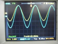
Here are details.
Yellow=output signal
blue=input signal
Vups=+/-50v
Offset=5mV
Idle cur.=70mA
One pair 2sc5200/a1943
Dummy=6R
Attachments
-
 DSC09029.JPG555.9 KB · Views: 154
 -
 DSC09028.JPG577.7 KB · Views: 138
 -
 DSC09027.JPG601.2 KB · Views: 130
 -
 DSC09026.JPG567.9 KB · Views: 136
 -
 DSC09018.JPG562.8 KB · Views: 410
 -
 DSC09015.JPG568.4 KB · Views: 424
 -
 DSC09014.JPG571.1 KB · Views: 443
 -
 DSC09012.JPG575.8 KB · Views: 466
 -
 DSC09011.JPG586 KB · Views: 509
Last edited:
Thimios,
It doesn't look like you could track the signal much better than that in the actual audio range we can hear. The question is can you truly hear a difference between this input circuit and the Krypton-ND or Krypton-C ? I think that is the final test, the ears will tell us if there is no difference. If not the simpler of the two circuits would be the winner in my mind.
It doesn't look like you could track the signal much better than that in the actual audio range we can hear. The question is can you truly hear a difference between this input circuit and the Krypton-ND or Krypton-C ? I think that is the final test, the ears will tell us if there is no difference. If not the simpler of the two circuits would be the winner in my mind.
Thimios,
It doesn't look like you could track the signal much better than that in the actual audio range we can hear. The question is can you truly hear a difference between this input circuit and the Krypton-ND or Krypton-C ? I think that is the final test, the ears will tell us if there is no difference. If not the simpler of the two circuits would be the winner in my mind.
There is no audible difference. This is the simplest to build now that the correct values have been determined. The offset is solid without a servo. As OS said. The perfect IPS for a first timer
I want to know listening impression about Symetri and Spooky. I think they are good in the low frequency.
Exactly!I want to know listening impression about Symetri and Spooky. I think they are good in the low frequency.
Bimo,that's it!
Symetri is another good one at low frequency.
This is the first impression from a little listening test.
Terry,
I agree. I think that Pete has reached so low in distortion that I don't think that even those who think they have golden ears can hear a difference at this level. So simple and stable should win in the end at this level. If the circuit is stable over very long periods of time then the use of a servo to keep it that way seems unnecessary. Pete can answer that last question, will the Symetri still be stable 20 years from now or will some dc offset creep in over time?
I agree. I think that Pete has reached so low in distortion that I don't think that even those who think they have golden ears can hear a difference at this level. So simple and stable should win in the end at this level. If the circuit is stable over very long periods of time then the use of a servo to keep it that way seems unnecessary. Pete can answer that last question, will the Symetri still be stable 20 years from now or will some dc offset creep in over time?
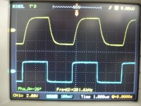
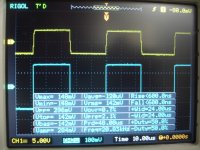
Here are details.
Yellow=output signal
blue=input signal
Vups=+/-50v
Offset=5mV
Idle cur.=70mA
One pair 2sc5200/a1943
Dummy=6R
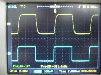
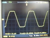
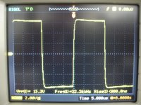
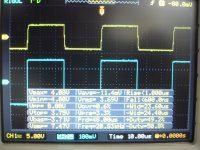
picture #4 - Still4given's overload did not exhibit the slight "sticking" I see ?
He ran at the higher input currents. R24/25 - R28/29 =68R and a corresponding
increase in the two LTP's current (@150R on the trimmers =1.4ma) ,
might alleviate this.
This also could be the 1943/5200 OPS "errata" with just one pair.
Still4given used two pair FET and the big slewmonster.
This IPS is not fully self clamping with ultra low Ib like the kypton ND !
In these metrics the symetri is a Ford mustang and the ND is Ferrari ....
Not a big issue , but why not explore it ?
OS
Exactly!
Bimo,that's it!
Symetri is another good one at low frequency.
This is the first impression from a little listening test.
Can you show me, harmonic distribution of 100 Hz sine on Symetri?
I want to know if H3 is dominant or not.
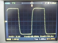
Ok i will increase the LTP current at 1.4mA and test clip again.picture #4 - Still4given's overload did not exhibit the slight "sticking" I see ?
He ran at the higher input currents. R24/25 - R28/29 =68R and a corresponding
increase in the two LTP's current (@150R on the trimmers =1.4ma) ,
might alleviate this.
This also could be the 1943/5200 OPS "errata" with just one pair.
Still4given used two pair FET and the big slewmonster.
This IPS is not fully self clamping with ultra low Ib like the kypton ND !
In these metrics the symetri is a Ford mustang and the ND is Ferrari ....
Not a big issue , but why not explore it ?
OS
edit:My clipping test is at 20KHz ,i don't know what frequency Terry test this.
A Ford mustang?🙄
I prefer Ferrari😎
Last edited:
- Home
- Amplifiers
- Solid State
- Slewmaster - CFA vs. VFA "Rumble"