A nice empirical find, still4given.
One of the things about the Baxandall is that it is not fully on at low voltages, so there can be strange things happening before the amplifier comes fully on.
One of the things about the Baxandall is that it is not fully on at low voltages, so there can be strange things happening before the amplifier comes fully on.
OS, remember the Baxandall pair eliminates Ccb. In your other designs the Ccb of the VAS was loading the output stage. If you're using cascoded predrivers those will also have highly reduced capacitance. In such a case the VAS node probably has less than 1pF of capacitance more from the trace parasitics! The lack of capacitance here can cause oscillation. Maybe this is your problem?
That is what the capacitors Still4given added did ? Now the OPS has it's
desired (required 😀) capacitance.
OS
So I can understand, are you saying this compensation actually belongs on the OPS? Why don't I see these issues with the other IPS?That is what the capacitors Still4given added did ? Now the OPS has it's
desired (required 😀) capacitance.
OS
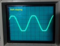
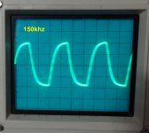
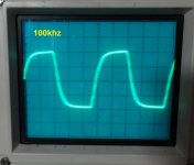
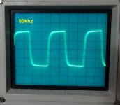
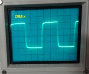
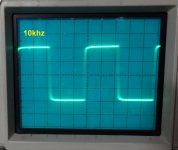
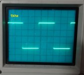
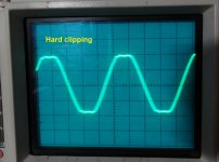
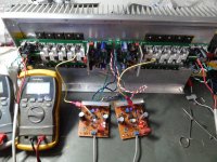
Here are some screen shots of the scope. +-57V rails. Clips at 33V into 8R load. Square waves measured at 12Vac output.
It has a little oscillation when it hard clips. There are also some little stripes in the rising leg of the square waves at higher frequencies. Maybe some more fine tuning is in order.
Blessings, Terry
Attachments
Terry, I have to say I'm amazed at your "production rate" of all the different kinds of IPS'es and amps.
His capacitors affect the VAS gain and phase. Consider the corner frequency of the 820R/10pF network that was created when he added the capacitors.
Also think of what happens if you have 1k base stoppers on Q9 and Q14. Well wait, you already do, you have 22R and 820R, and the capacitance of the KSC1845 collector is almost nothing. The 10p capacitor probably absorbs some of the base current at RF. The base current of these transistors is initially small but rises rapidly at RF.
I'm not sure if this relates fully to the cause of the oscillation but it may help the investigation.
Terry, I have to say I'm amazed at your "production rate" of all the different kinds of IPS'es and amps.
Thanks, all in the spirit of learning and of course, FUN!
I'm not sure if this relates fully to the cause of the oscillation but it may help the investigation.
Thanks for the explanation. I've only had one other IPS do this and that was Valery's Low TIM hybrid IPS. He of course worked with me and we got it all straightened out. Plays perfectly now.
It's funny, that when I scoped this IPS alone the square waves were pretty crisp all the way to 100khz. Now that it is hooked up through the OPS they get a bit rounded up high. It doesn't seem to affect the sound though. I have had it playing for a couple of hours now and it really sounds good.
Blessings, Terry
Attachments
OS,
Glad to see you putting something together for yourself. Getting everything to fit in the box is always the hardest part.
E
Glad to see you putting something together for yourself. Getting everything to fit in the box is always the hardest part.
E
Oops, sorry - long rainy day plus a little bit of a flu "switched me off" at some point, so I dropped out of the discussion 
 😀
😀
Cool, it works 🙂 Right, OPS slightly "slows down" the whole loop, but that's ok, more power -> less speed.
The whole thing may be still slightly optimized in terms of best behavior at HF, but even the way it is now (very slight "undershoot" at very highs) should sound very cool, being a highly linear topology with lots of potential
😀Cool, it works 🙂 Right, OPS slightly "slows down" the whole loop, but that's ok, more power -> less speed.
The whole thing may be still slightly optimized in terms of best behavior at HF, but even the way it is now (very slight "undershoot" at very highs) should sound very cool, being a highly linear topology with lots of potential
How 'bout modular?
OS, just trying to think literally "out of the box" 😛
Is the pre-amp case tall enough for the "hulk" trafo?
You could make an external PSU. Having then a lot of space for the biggest slewmasters, ips modules, protection/control, etc. in the bigger compartment with the heatsinks 😎
Connecting the blocks with a thick DC cable. Pretty "high-end" approach BTW 🙄
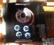
Nice case + PS .... caps are too big. 🙁
Tried every position , no room for slewmasters.
OS
OS, just trying to think literally "out of the box" 😛
Is the pre-amp case tall enough for the "hulk" trafo?
You could make an external PSU. Having then a lot of space for the biggest slewmasters, ips modules, protection/control, etc. in the bigger compartment with the heatsinks 😎
Connecting the blocks with a thick DC cable. Pretty "high-end" approach BTW 🙄
Case woe's ....
It's 125mm high inside. Almost 300mm deep. Caps are 135+mm high.
I would love to use the caps , the preamp case was a shipping mistake from
the "big case" donor (not my case) .... lots of confusion, thought the pre-amp
case was the big one - both came from China.
You must watch these Chinese vendors , in my case they drilled the
back panel for input/output/power ... but no front power switch/LED.
The exact opposite of what they shown in the listing. No holes for the
feet (they did include the feet). A really heavy case - what they did
was actually better for me (less holes in total).
I suppose I'll PM some people. Try to get some snap-in caps.
I want lots of room in this case to swap IPS's ... then I can be the one to
experience oscillators. Or ... be smart with a mini-ops , and test first.
OS
How tall and deep is the case inside?
It's 125mm high inside. Almost 300mm deep. Caps are 135+mm high.
I would love to use the caps , the preamp case was a shipping mistake from
the "big case" donor (not my case) .... lots of confusion, thought the pre-amp
case was the big one - both came from China.
You must watch these Chinese vendors , in my case they drilled the
back panel for input/output/power ... but no front power switch/LED.
The exact opposite of what they shown in the listing. No holes for the
feet (they did include the feet). A really heavy case - what they did
was actually better for me (less holes in total).
I suppose I'll PM some people. Try to get some snap-in caps.
I want lots of room in this case to swap IPS's ... then I can be the one to
experience oscillators. Or ... be smart with a mini-ops , and test first.
OS
That's going to be pretty snug inside no matter how you build it with that transformer. You won't get an input and output together on a heat sink.
OS, just trying to think literally "out of the box" 😛
Is the pre-amp case tall enough for the "hulk" trafo?
You could make an external PSU. Having then a lot of space for the biggest slewmasters, ips modules, protection/control, etc. in the bigger compartment with the heatsinks 😎
Connecting the blocks with a thick DC cable. Pretty "high-end" approach BTW 🙄
Little case isn't mine. 🙁
I love your big caps , but 8-12/ 8-10Kuf snap-ins would take less room.
2 groupings of 6 - one for each channel.
If you would not mind ... maybe a trade with another builder ? I would make
sure of a fair trade , as these Nichicons are PREMIUM ! 😱
(no used caps - or generics).
OS
Would you be able to lay the caps on their sides at the back of the case if the input boards were on the heat sink?
Little case isn't mine. 🙁
I love your big caps , but 8-12/ 8-10Kuf snap-ins would take less room.
2 groupings of 6 - one for each channel.
If you would not mind ... maybe a trade with another builder ? I would make
sure of a fair trade , as these Nichicons are PREMIUM ! 😱
(no used caps - or generics).
OS
Whatever brings the right result - is good 😉
That's going to be pretty snug inside no matter how you build it with that transformer. You won't get an input and output together on a heat sink.
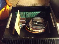
The IPS goes at a right angle to the OPS !!
Actually - the case is about 360mm deep , 285mm wide , 135mm tall (inside).
. I just estimated before. No mm/CM tape.
OS
If you like Valery's idea of the remote supply case I can make you something to match what you have. Too bad we don't have trucks running near you.
If you like Valery's idea of the remote supply case I can make you something to match what you have. Too bad we don't have trucks running near you.
I just did some more precise "fitting'". Slewmaster's fit heatsink's horiz.
with 25mm to spare.
A piece of aluminum 175 X 125mm with an angle at the bottom will
mount all those snap-in's - just 2-3 holes in the enclosure bottom.
(white epoxy board below).
It should work , and be pretty. 😀
PS - valery's protect/softstart could mount on the other side of the white board.
OS
Attachments
Last edited:
- Home
- Amplifiers
- Solid State
- Slewmaster - CFA vs. VFA "Rumble"