I will "make it so" .... HF noise , .01u ??? They can be very low
voltage (cheap) .. no big issue.
To rate this amp .... it has the THD20 of the "leach/spooky" and
even better slew/ SW behavior than the "NX" (diamond buffered).
Between those 2 factors ... it is best (at least in sim).
OS
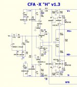
This will be new standard DIY amp I'm quite sure, just be sure to prepare and test sch to the last detail. Also all in one PCB should be designed by Alex at some point.
Use 0,1uF for IR diodes decoupling and please lower input resistor to 10-22k for many reasons, no need to have 47k.
This will be new standard DIY amp I'm quite sure, just be sure to prepare and test sch to the last detail. Also all in one PCB should be designed by Alex at some point.
Use 0,1uF for IR diodes decoupling and please lower input resistor to 10-22k for many reasons, no need to have 47k.
Added the caps ... (C5/6 - below 1) , 22k - R2 . This will go to board.
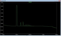
I looked over your "first one" thread. My FFT (below 2) seems to nearly
match your (outputs). It does all this at 7 PPM !
I'm still amazed how something this simple can match the spooky
leach with it's 80 components !
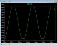
EDIT - (below 3) almost forgot clipping .... 100mv symmetrical 62.5V @ 70V rails.
OS
Attachments
Last edited:
Added the caps ... (C5/6 - below 1) , 22k - R2 . This will go to board.
I looked over your "first one" thread. My FFT (below 2) seems to nearly
match your (outputs). It does all this at 7 PPM !
I'm still amazed how something this simple can match the spooky
leach with it's 80 components !
EDIT - (below 3) almost forgot clipping .... 100mv symmetrical 62.5V @ 70V rails.
OS
You can improve a bit if you connect R17, R18 to the Q1, Q2 emitters respectively(local feedback), instead to the ground, and you need to increase the resistors value, probably.
Impressive spec's for so few components.
Have you tried changing some of the values to simulate component tolerances? For example, the two feedback networks. I know we can match components but they can never be exact.
Just wondering how well this one would translate to the real world and how sensitive it is to component variation.
Have you tried changing some of the values to simulate component tolerances? For example, the two feedback networks. I know we can match components but they can never be exact.
Just wondering how well this one would translate to the real world and how sensitive it is to component variation.
Added the caps ... (C5/6 - below 1) , 22k - R2 . This will go to board.
I looked over your "first one" thread. My FFT (below 2) seems to nearly
match your (outputs). It does all this at 7 PPM !
I'm still amazed how something this simple can match the spooky
leach with it's 80 components !
EDIT - (below 3) almost forgot clipping .... 100mv symmetrical 62.5V @ 70V rails.
OS

You can improve a bit if you connect R17, R18 to the Q1, Q2 emitters respectively(local feedback), instead to the ground, and you need to increase the resistors value, probably.
tried that with both positive (reversed) FB and NFB from VAS OP
to IP emitters ... could not even budge that 7ppm figure except if
I lowered R <47K. (no effect).
Have you tried changing some of the values to simulate component tolerances? For example, the two feedback networks. I know we can match components but they can never be exact.
Swapped Zetex / to-126 / and ksa/c xx models for IP pair, only needed
to re-trim R5 /R12 for offset , CLG stays 55db@1k UG @ 2+mhz.
Also , swapped Cordell MJE340/350 , KSA/C 1381/3503 for VAS (no real change) - had to readjust OPS bias.
C13/14 between 100p and 22p = 75-400 V/us slew (no ring).
R7-10 (CFB networks) tried 1.5K/68R .... slew increases (minimum C13/14=
27p - no ringing) ... 1K/33R - same slew/stability with 33p C13/14.
Also tried different Hawksford Re's (R16/21) , @ 100R ... IP pair (I) reduced to 1.4ma - same performance.
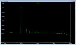
(below 1) ... with more "VAS abuse" (call the
 ) , 33K for R17/18
increases H2 and lowers H3 !
OS
Attachments
Bullet proof design for DIY abusers 😀
First One amps now running for 6 moths without any report of error, VSSA even in greater numbers for more than year without any problems.
No offset problems at higher temperatures, no parts matching critical here.
First One amps now running for 6 moths without any report of error, VSSA even in greater numbers for more than year without any problems.
No offset problems at higher temperatures, no parts matching critical here.
Bullet proof design for DIY abusers 😀
First One amps now running for 6 moths without any report of error, VSSA even in greater numbers for more than year without any problems.
No offset problems at higher temperatures, no parts matching critical here.
Even this slightly "embellished" CFA design is about as easy as your
typical LM3886 chip amp project.
It might not even "fry"
 if they forget the compensation. 😀
OS
OS,
I'm expecting a lot more out of these designs than I would with a simple 3886 Gainclone.
LazyCat,
I still have a pair of your VSSA boards I haven't used yet but am planning to try on some tweeters above the OS designed CFA-XH and his Slewmaster section for the bass/mid range speaker. Should be a nice combination with an electronic xo working together. I still can't get over how small the VSSA boards are.
OS,
I'm expecting a lot more out of these designs than I would with a simple 3886 Gainclone.
LazyCat,
I still have a pair of your VSSA boards I haven't used yet but am planning to try on some tweeters above the OS designed CFA-XH and his Slewmaster section for the bass/mid range speaker. Should be a nice combination with an electronic xo working together. I still can't get over how small the VSSA boards are.
And you will get more .... this one will be the smallish 76mm^2 IPS.
What's the vssa PCB , 76 X 100mm ??
OS
The VSSA boards are only 80mm x 60mm, really small for 100watts output.
Let me correct you, VSSA PCB measures 50 mm x 60 mm and it gives 120 W/4 Ohm, more than 300 went to travel the world, the variety of countries were really impressive.

My Slewmonster boards finally arrived. They really look really nice. Can't wait to get started on them. Thanks Jason!
I also received a pair of Jason's VSSA through-hole boards so that will be my first CFA-Slewmonster build.
Blessings, Terry
I also received a pair of Jason's VSSA through-hole boards so that will be my first CFA-Slewmonster build.
Blessings, Terry
Attachments
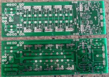
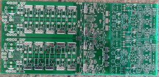
Ufff... will require "some" soldering, I'm afraid 😉 🙂
Excellent quality boards
Mmmmm, soldering, my favorite part.
To anyone,
Question, do C103 & C106b see full rail? I bought 100v parts but they will need some help to fit.
Thanks, Terry
Mmmmm, soldering, my favorite part.
To anyone,
Question, do C103 & C106b see full rail? I bought 100v parts but they will need some help to fit.
Thanks, Terry
They see darn close to the full rail. I was able to find 100V 330uF in a size that fits those locations but not 470uF. You should be OK with a somewhat lower capacitance there on the multiplier reference.
They see darn close to the full rail. I was able to find 100V 330uF in a size that fits those locations but not 470uF. You should be OK with a somewhat lower capacitance there on the multiplier reference.
Consider the multiplier is capacitance times Hfe. A 220uf with E grade
KSA/C pairs will far exceed even 470uF with MJE340/350 pairs.
You even have the option to use some of the high Hfe to-92L
Japanese semi's. Most IPS's only use 15-20ma per rail.
OS
Consider the multiplier is capacitance times Hfe. A 220uf with E grade
KSA/C pairs will far exceed even 470uF with MJE340/350 pairs.
You even have the option to use some of the high Hfe to-92L
Japanese semi's. Most IPS's only use 15-20ma per rail.
OS
Could you please explain a little further? Are you saying that the 470uf is necessary?
Thanks, Terry
Could you please explain a little further? Are you saying that the 470uf is necessary?
Thanks, Terry
A low gain transistor times the capacitance , for example ....
470uF X a mje 350's 70Hfe would equal 33kuf in "virtual" capacitance.
A better ksa1381"E" at 160Hfe .... the 160 X 470 would equal 75Kuf.
You can substitute lower multiplier capacitance for more active device
gain , so with the KSA ... a 220uf would make for 35Kuf "virtual" capacitance.
This OPS is not designed for it , but ... a darlington could allow a
1uf cap to appear larger than a 470u !!! (1 x 50K Hfe) 😱
PS - to explain another way - transistor gain is more important than cap size.
IPS rails are connected to the transistor , not the cap !
OS
Last edited:
- Home
- Amplifiers
- Solid State
- Slewmaster - CFA vs. VFA "Rumble"