Let's do a blind test!
Look at this .
25Vpp /200KHz/4R DUMMY LOAD.
I want opinions.Then I will reveal the exact version.
Thimios.

😱 😎
Did you modify the schematic?
No bimo this is from an unmodified schematic..😱 😎
Did you modify the schematic?
No bimo this is from an unmodified schematic..
I see. May be my amp can do that. But I do not have good square wave signal generator up to 200kHz. Anyone have simple schematic that can produce good square wave signal up to 200kHz?
Let's do a blind test!
Look at this .
25Vpp /200KHz/4R DUMMY LOAD.
I want opinions.Then I will reveal the exact version.
Thimios.
i do not think it is cfa-x....
Here's hoping we see some of OS's refinements to the CFA-X from the 'other' thread here soon (the CFA-XH)... I think I'd jump on that right away! A giant VSSA 😎.
OK , I will begin.
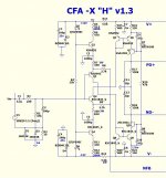
(below 1) is the "H" version of the CFA-X.
This IPS "burns up the road".
5-12ppm (1k/20k) with 400v/us slew ( in a more "tame" mode).
It will run with NO compensation ! Amazing.
Easy to make the IPS , just graft my already- made Hawksford layout
to the "CFA-X". 🙂
Some say I should add the servo/floating CCS plus cascodes to the
IP pair. Nope ... "KISS" (keep it stupid simple), is the better way.
Easier just to use something like D667a/B647a to "harden" the IP
pair. (many other choices for 10 Cob - 100Vceo - 1A devices).
OS
Attachments
Ostripper,
Hoping to recieve my Slew boards this week and then I've to decide which IPS board I take but you've designed so many.Don't know which one to take anymore.
Hoping to recieve my Slew boards this week and then I've to decide which IPS board I take but you've designed so many.Don't know which one to take anymore.
Last edited:
Ostripper,
Hoping to recieve my Slew boards this week and then I've to decide which IPS board I take but you've designed so many.Don't know which one to take anymore.
I'm kind of leaning toward the original "CFA-X" -or this update to it ,for my
own OPS's.
I love the hawksford sound (so does luxman - even their preamps
have this for op). I must satisfy my UV/red led fetish ... this
amp must look "tubish" 😀 .
(below is the reason) !! Mama ... I forgot the caps !! 😱
OS
Attachments
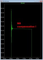
I would not try this in the real world 😀 ... but it is a good
example of this circuits "slop" factor (VERY wide margin for error).
Also , don't try shunt comp. with the "gnome" (dadod has one oscillating
on the CFA thread). On this PCB , I will allow for either miller or shunt ...
just to be careful.
PS - the slew on my last attachment was 1.2KV+/us (estimate) with 6mhz UG. that's as
far as these models can go. (amp limited by Cob)
OS
Last edited:
So OS,
I assume you wouldn't really want that ringing on the square wave even at that insane slew rate, will there be some compensation scheme to tame that circuit?
I assume you wouldn't really want that ringing on the square wave even at that insane slew rate, will there be some compensation scheme to tame that circuit?
So OS,
I assume you wouldn't really want that ringing on the square wave even at that insane slew rate, will there be some compensation scheme to tame that circuit?
Your suggestion creates a interesting possibility.
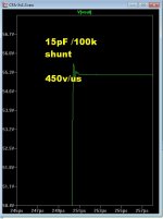
(below 1) is realistically fast. while it does slightly ring , it is stable ...
I saw some of the more aggressive tests that thimios did.
With trimmable capacitors like Thimios used , you could just "dial in"
your desired slew.The predicted range would be 60V/uS to over 600V/us
(with the trimmer).
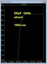
(below 2) is 68p comp. (slow - like a VFA😀) , with a 100pf mica
trimmer cap (below 3) .... interesting comparisons could be achieved.
Attachments
I must say those are the first adjustable caps I have ever seen. For those of us who don't currently have access to a nice O'scope will the bom and specific part numbers and values give us a workable solution without having to worry about oscillations?
Last edited:
I must say those are the first adjustable caps I have ever seen. For those of us who don't currently have access to a nice O'scope will the bom and specific part numbers and values give us a workable solution without having to worry about oscillations?
Those with scopes could trim to perfection and enlighten the rest. 🙂
A "safe" value is 100k/27-33pF - no ringing at all ...300V slew.
I have started the PCB. it will also appeal to "tweakers" ... multiple
compensation options.
PS = "adjustable caps" .... open up a hi-fi tuner or receiver, the rf "front end" will have them.
OS
Attachments

Last edited:
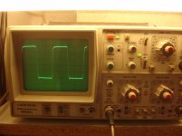
Let's do a blind test!
Look at this .
25Vpp /200KHz/4R DUMMY LOAD.
I want opinions.Then I will reveal the exact version.
Thimios.
 ok guys this is UNMODIFIED Gnome.....
Out trans.2sc3264,a1295.
Attachments
Last edited:
D5, D6 needs decoupling, lower noise tooOK , I will begin.
(below 1) is the "H" version of the CFA-X.
This IPS "burns up the road".
5-12ppm (1k/20k) with 400v/us slew ( in a more "tame" mode).
It will run with NO compensation ! Amazing.
Easy to make the IPS , just graft my already- made Hawksford layout
to the "CFA-X". 🙂
Some say I should add the servo/floating CCS plus cascodes to the
IP pair. Nope ... "KISS" (keep it stupid simple), is the better way.
Easier just to use something like D667a/B647a to "harden" the IP
pair. (many other choices for 10 Cob - 100Vceo - 1A devices).
OS
R2 lower to 10-22 k
Feedback resistor sets the gm, so indeed if the feedback resistor is of the appropriate value, you can in theory skip the comp cap. However, I think in these cases you will be relting on the intrinsic capacitance of the TIS/TAS and any capacitance load from the TIS/TAS output to ground (can be 10s of pF in a practical amp)
D5, D6 needs decoupling, lower noise too
R2 lower to 10-22 k
I will "make it so" .... HF noise , .01u ??? They can be very low
voltage (cheap) .. no big issue.
To rate this amp .... it has the THD20 of the "leach/spooky" and
even better slew/ SW behavior than the "NX" (diamond buffered).
Between those 2 factors ... it is best (at least in sim).
OS
- Home
- Amplifiers
- Solid State
- Slewmaster - CFA vs. VFA "Rumble"