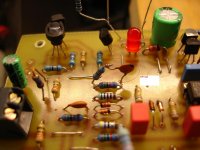
I can say that most commercial amplifiers uses these ceramic capacitors for all stages.Don't generalize ceramic caps, some are very good for audio, as NP0 or C0G.
Damir
Thimios.
Good , as long as they aren't ceramic. Ones like that would even be better
for Cdom1/2 (instead of ceramic).
BTW - a newer NAD is on the drawing board.
I'll squeeze this on the smallest IPS board (76.2 X 76.2mm) ,
and make it very "pretty" 😀 .
OS
You add R11 and R15. It is easy to measure VAS current 😉.
For thimios
Dear thimios
You actually pave the way first in a very interesting comparison sound amplifiers developed by the great master ostripper
The first is always the hardest . Very disappointed that you burned a couple of 21195/96 .
When you first start the amplifier , particularly when configuring a correction , it is important to include the amplifier through the series included incandescent bulb , power 60-100 W ( incandescent bulb but not energy efficient ) with the primary winding of the power supply transformer . If the amplifier lamp burns brightly , then there is a fault or excitation amplifier. Lamp with intact amplifier depending on the initial current can shine a little - a little. This simple method helps to keep the elements of the amplifier.
For thimios
Dear thimios
You actually pave the way first in a very interesting comparison sound amplifiers developed by the great master ostripper
The first is always the hardest . Very disappointed that you burned a couple of 21195/96 .
When you first start the amplifier , particularly when configuring a correction , it is important to include the amplifier through the series included incandescent bulb , power 60-100 W ( incandescent bulb but not energy efficient ) with the primary winding of the power supply transformer . If the amplifier lamp burns brightly , then there is a fault or excitation amplifier. Lamp with intact amplifier depending on the initial current can shine a little - a little. This simple method helps to keep the elements of the amplifier.
Thanks for reply.
I know all these my friend ,I used all these repairing televisions smps, but testing amplifiers at 200 khz full power is a high risk anyway.

Thimios.
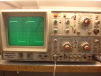
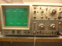
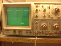
Today NAD, Spooky tested with 3.3uH and 5.6uH shorted inp.OS or Thimios, can you short the amp input with a 5uH inductor to see if it oscillates? Also try higher and low inductor values if possible.
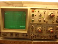
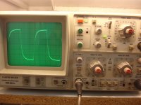
I didn't see any oscillation.
Spooky also tested with small inp signals.(80mV RMS)
1)1KHz
2)3.2KHz
3)5KHz
4)10KHz
5)20KHz
6)30KHz
7)40KHz
8)70KHz
9)100KHz
10)200KHz
11)450KHz
Attachments
-
 DSC07609.JPG568.6 KB · Views: 686
 -
 DSC07619.JPG593.7 KB · Views: 207
 -
 DSC07618.JPG607.8 KB · Views: 194
 -
 DSC07617.JPG523.4 KB · Views: 192
 -
 DSC07616.JPG602.4 KB · Views: 190
 -
 DSC07614.JPG604.1 KB · Views: 208
 -
 DSC07613.JPG598.7 KB · Views: 571
 -
 DSC07612.JPG598.5 KB · Views: 586
 -
 DSC07611.JPG615.8 KB · Views: 608
 -
 DSC07610.JPG532.3 KB · Views: 626
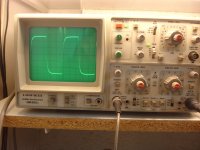
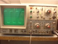
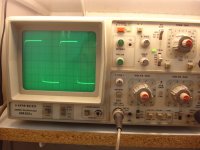
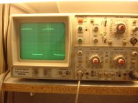
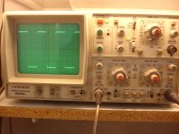
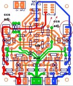
450 KHz and the recommended R.C unfortunately with ceramic cheap
Attachments
Last edited:
to Thimnios,
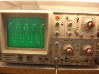
When driving the amp to clipping and when the amp comes out of clipping,there are not any signs of instabillity ok?
also have you tried a low level square wave test on a 8ohm + 1uF (or 2,2uF) dummy load?any stability issues here?
When driving the amp to clipping and when the amp comes out of clipping,there are not any signs of instabillity ok?
also have you tried a low level square wave test on a 8ohm + 1uF (or 2,2uF) dummy load?any stability issues here?
If i remember correctly the ceramic with black cap is NP0 and some say that they are reasonably good for use in CDOM and compensation, even for preamp tone control caps.
The resin dipped multilayer C0G ceramics are hard to physically identify whether they C0G or X7R or other.
Anyone done experiments to see if silver mica is greatly superior?
Regards
The resin dipped multilayer C0G ceramics are hard to physically identify whether they C0G or X7R or other.
Anyone done experiments to see if silver mica is greatly superior?
Regards
No there isn't any instabillity when ampl.clip.to Thimnios,
When driving the amp to clipping and when the amp comes out of clipping,there are not any signs of instabillity ok?
also have you tried a low level square wave test on a 8ohm + 1uF (or 2,2uF) dummy load?any stability issues here?
I haven't try this .
Thimios.
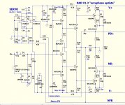
"NEW" NAD CFA ....
Same great design ...
- slightly less current feedback , will allow for more precise servo control.
The Zener dropping resistors had to be changed to 4.7K (60V) to
compensate for the servo's "hunger" (more mA) 😀 .
- non-inverting servo feedback to the current node. It is like the
accuphase 210e OEM amp. They used 2.2k for FB , this will only
allow 5V MAX offset in case of a servo failure (safety first) 🙂 .
-trimmers for CCS's , no more swapping resistors !
-better star ground
-"magic resistors" for the hawksford .... Memory Distortion Philosophies - Part 5 : Circuits, continued
with these-you can calculate the actual cascode current , as well.
-"pretty" symmetrical layout.
By adjusting the trimmers , you can "lighten the load" on the servo ....
since the diamond gender mismatch is the source of the offset.
Might have it done tonight ...
OS
Attachments
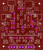
Used every square CM ... whoa !
Pullin' hair 😱 .... but it's lay...ed out... 😀
(below) The servo is a 2 stage with .2HZ Fc. Nearly as many parts
as the Leach (spooky).
It should please all.
In order to balance the gender mismatch (PNP/NPN) on the diamond IP
stage , The NPN is running at 1.25ma ... while the PNP is 1.5mA.
Like this, the servo just needs 100uA to correct offset. With all set equal ,
the servo needs 1mA+ to do the job (works harder).
If you closely matched the P/N on a curve tracer - no issue.
Anybody designing a CFA without a servo and dual adjustable current sources
is making a "toy" of an amp.
DO NOT worry , if you are deaf and dumb .... and put any junkbox "partz"
in the input stage , the buffered low Z servo will "clean up" after you.
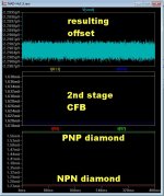
(below 2) is when you trim the CCS's ...
you still get uV offset... no signal - worst I got was 6mV at LF - 1.8mV typical. 🙂
PS - this exact setup does 15-20ppm ... best combo of servo/FB/component
choices - more tolerant of model "swaps" , as well. Still 10 active devices.
OS
OS
Pullin' hair 😱 .... but it's lay...ed out... 😀
(below) The servo is a 2 stage with .2HZ Fc. Nearly as many parts
as the Leach (spooky).
It should please all.
In order to balance the gender mismatch (PNP/NPN) on the diamond IP
stage , The NPN is running at 1.25ma ... while the PNP is 1.5mA.
Like this, the servo just needs 100uA to correct offset. With all set equal ,
the servo needs 1mA+ to do the job (works harder).
If you closely matched the P/N on a curve tracer - no issue.
Anybody designing a CFA without a servo and dual adjustable current sources
is making a "toy" of an amp.
DO NOT worry , if you are deaf and dumb .... and put any junkbox "partz"
in the input stage , the buffered low Z servo will "clean up" after you.
(below 2) is when you trim the CCS's ...
you still get uV offset... no signal - worst I got was 6mV at LF - 1.8mV typical. 🙂
PS - this exact setup does 15-20ppm ... best combo of servo/FB/component
choices - more tolerant of model "swaps" , as well. Still 10 active devices.
OS
OS
Attachments
OS, I'm most interested in the Spooky Leach and the latest NAD. Can you put up a zip of your current Sprint files for at least these two, if not all that are complete, please?
I'm thinking if my supplier can score a panel I can make one big layout with two or more IPSs on it and just break them apart. Thoughts on that?
Also, OPS boards are shipped and on their way. Only difference between what I posted as final files and these are slightly different position of the driver heat sink support pads. I will post a pic when they arrive.
Last edited:
Jason,
Are your extra output sections spoken for yet? I know I was talking to still4given about getting some of his boards but I think he has been up to his eyeballs in trying to get some of Bonsai's NX amplifiers to function correctly so I don't think he has started any of these output sections yet. It seems that your board design is the completed thoughts of OS and I don't see that it is going to change. Let me know what you want to do, I know I am only one of many who want to pursue this.
Steven
I have ordered some boards as well. I will have a couple pairs available once I get them and make sure they are functional. I hope not to send along any more boards that don't do what they are designed to do. While I am waiting for them I will try to etch some boards for the front end. Hoping to do the Symasui first.
I am planning my first set being made of e-waste parts, at least mostly anyway. I will attempt to make use of my VSSA boards for a test IPS by only stuffing the input and VAS components. Hopefully I can 'prove' at least one quickly.
Terry, I think there have been more eyes on this one to catch issues and the basic layout has already been built. I doubt these will be duds with any issues.
Terry, I think there have been more eyes on this one to catch issues and the basic layout has already been built. I doubt these will be duds with any issues.
I had wondered if the VSSA front end would work with these. I thought the feedback was different with the VSSA. I also have some SymaSym boards and wondered if those could be utilized.
I'm waiting to see that the NAD design is completed and that is what I am interested in, at least for now unless someone shows the Spooky is going to be superior in sound and not just in specifications.
- Home
- Amplifiers
- Solid State
- Slewmaster - CFA vs. VFA "Rumble"