Your PCB looks like it wants to "sing".
Thank you for the Macro's . BTW.
no problem OS just delete the one you are not gonna use they are too many duplicated 😛
OS
Vargas
Nice work Vargas but i can't follow.
I need a single side pcb to be able testing.
I think that i must wait this time.😱
BTW nothing wrong with smd for me.😉
I think that is the only way these days.😎
I need a single side pcb to be able testing.
I think that i must wait this time.😱
BTW nothing wrong with smd for me.😉
I think that is the only way these days.😎
Nice work Vargas but i can't follow.
I need a single side pcb to be able testing.
I think that i must wait this time.😱
BTW nothing wrong with smd for me.😉
I think that is the only way these days.😎
thank you I just gonna "yolo" and I order a few PCB last night they are in process right now I will keep inform 🙂
Vargas
Could 10 boards be purchased from pcbway and shipped for less than 10 dollars per board to 10 people at least for testing. I would rather spend that much instead of making a single sided board, just putting out a idea, I will put my 10 dollars up right now. Total cost is 62 dollars gold on blue including shipping.
Last edited:
Could 10 boards be purchased from pcbway and shipped for less than 10 dollars per board to 10 people at least for testing. I would rather spend that much instead of making a single sided board, just putting out a idea, I will put my 10 dollars up right now.
hey Krisfr I only order a few to prototype only sadly I don't have scope or any testing devices to check "thimios is really good with that" I only can use audio signal from my PC to tested after I get the PCB and put it together and tested I will inform if my design was successful or not no matter what happen I'll keep posting oh yeah in my case the total cost was $18.00 USD with shipping Puerto Rico was $11 bucks and $2 dollars PayPal fee included and boards $5 bucks for 5 PCB for proto only I be like yolo! well wish me luck guys 🙂
Note: I don't have any intention to do a group buy just to let you know this is for me to enjoy 80's music especially 😛
Vargas
Nice work Vargas but i can't follow.
I need a single side pcb to be able testing.
I think that i must wait this time.😱
BTW nothing wrong with smd for me.😉
I think that is the only way these days.😎
The Thimios , I am going to make smaller modular (SMD) versions of
Vargas's VFA and the other CFA. Single sided 60 X 60mm ones.
Both "greenamp" variations.
The greenamp itself is being advanced daily.
Just one 60-0-60V supply for class H (or class OS) 😀.
It is like a OUTPUT TRACKING CAP MULTIPLIER now - unique.
PS - actually a tracking CFP series regulator.
OS
Last edited:
I
I love the smd building.
I think that i have enough experience.
That's what i say... I will wait😉The Thimios , I am going to make smaller modular (SMD) versions of
Vargas's VFA and the other CFA. Single sided 60 X 60mm ones.
Both "greenamp" variations.
The greenamp itself is being advanced daily.
Just one 60-0-60V supply for class H (or class OS) 😀.
It is like a OUTPUT TRACKING CAP MULTIPLIER now - unique.
PS - actually a tracking CFP series regulator.
OS
I love the smd building.
I think that i have enough experience.
Attachments
Last edited:
The Thimios , I am going to make smaller modular (SMD) versions of
Vargas's VFA and the other CFA. Single sided 60 X 60mm ones.
Both "greenamp" variations.
The greenamp itself is being advanced daily.
Just one 60-0-60V supply for class H (or class OS) 😀.
It is like a OUTPUT TRACKING CAP MULTIPLIER now - unique.
PS - actually a tracking CFP series regulator.
OS
Looking forward to the single sided too.
Blessings
I
That's what i say... I will wait😉
I love the smd building.
I think that i have enough experience.
I can't figure what everybody's issue is with SMD.
VZ does (almost) what I envision . TO-126 + electro's are through-hole.
I might go SMD SOT223 for the VAS/pre-drivers and cap multipliers.
Even big paralleled 10mm SMD Re's for the output board.
SMD solid caps are cheap to 63V for the zener references.
OPS= 50% and IPS = nearly 100% SMD.
I think they are easy.
Thimios , I see that smd op-amp , does not look too difficult.
OS
I haven't figured out the issues with SMD either. If you really want to do it the easy way stencils are cheap when ordered with the PC boards (I'll pass on the home etch stuff) which makes a very neat board, no globby solder joints.
I've been patiently waiting to see a finished version of the Greenamp. I want to try this thing! I've been looking into SMPS designs too, The hand wound Litz wire transformers look like a lot of fun to design!
I've been patiently waiting to see a finished version of the Greenamp. I want to try this thing! I've been looking into SMPS designs too, The hand wound Litz wire transformers look like a lot of fun to design!
I haven't figured out the issues with SMD either. If you really want to do it the easy way stencils are cheap when ordered with the PC boards (I'll pass on the home etch stuff) which makes a very neat board, no globby solder joints.
I've been patiently waiting to see a finished version of the Greenamp. I want to try this thing! I've been looking into SMPS designs too, The hand wound Litz wire transformers look like a lot of fun to design!
Dave Zan told me the single rail greenamp was a "stacker" OPS.
Like a "slacker".
You would lose the efficiency , but retain the SOA advantage (MO' power).
I put the 2 rail back as the plan.
I had a IDEA , the one and two supply "options" one one board. One design
was a variant of the other , so components could be added or omitted.
The one supply has the gobs of power , 5ppm THD 20k , and more heat.
The 2 supply is ultra efficient , 5ppm low power that jumps to 30ppm
in "hard"class H.
I gave Vargas the CFA greenamp schema , if he wants to play. All the IPS's
have really already been tested here , first prototypes.
The best of the best is the "Kypton ND" V2 , which is "greenamp CFA".
OS
Something to chew on ...
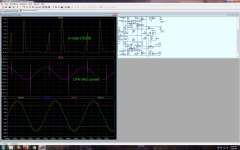
The voodoo of a non-switching output stage is really un - needed.
If you look at the middle VAS current waveform , you see it "glitches"
right as my class H + schottkey diodes switch. It is correcting all that and it still
can output 18ppm/ 4R/ 20khz.
In a triple EF , switching distortion at crossover is 1/10th that. The fast CFA
would easily error correct that without NS.
Another trade-off , add error correction or NS to the output stage and slow it
down or keep things simple and "smokin' fast. Any positive feedback loop you
add to the OPS is a negative.
The greenamp CFP trackers are much faster than the EF3. Before they kick in ,
the core EF3 is "virgin" and running at 30V.
So , up to 30V - you have a small slewmaster EF3.
Many options here , run dual mono 30-0-30V analog PS's for low rails. Get
one big 600W SMPS for both channel high rails. Have a light weight amp that can
put out easy 400w peaks. Or go with 2 SMPS's , my PSRR is way above 100db.
OS
Attachments
I can't figure what everybody's issue is with SMD.
VZ does (almost) what I envision . TO-126 + electro's are through-hole.
I might go SMD SOT223 for the VAS/pre-drivers and cap multipliers.
Even big paralleled 10mm SMD Re's for the output board.
SMD solid caps are cheap to 63V for the zener references.
OPS= 50% and IPS = nearly 100% SMD.
I think they are easy.
Thimios , I see that smd op-amp , does not look too difficult.
OS
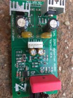
Not at all, the only difficult is here, Q1, Q2
Attachments
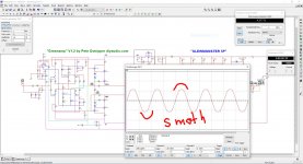
smooth Operator smooth Operator
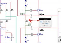
hey OS I think you mention that the IPS GreenampV1.2 is gonna clip "smoothly" yes is in fact correct awesome no harsh clip very nice 🙂 this is after 446 watt with 65V supply rails I misspell smooth on the note image xD
oh other thing I can't really adjust R25 to have a reading of 1.5 mA exactly I got 1.6 mA is that be ok and not need to be critical that value? I was think to increse the value of the trim pot CCS adj 1 and 2 to 1K maybe? let me know when you get a chance
Vargas
Attachments
Last edited:
hey OS I think you mention that the IPS GreenampV1.2 is gonna clip "smoothly" yes is in fact correct awesome no harsh clip very nice 🙂 this is after 446 watt with 65V supply rails I misspell smooth on the note image xD
oh other thing I can't really adjust R25 to have a reading of 1.5 mA exactly I got 1.6 mA is that be ok and not need to be critical that value? I was think to increse the value of the trim pot CCS adj 1 and 2 to 1K maybe? let me know when you get a chance
Vargas
R25 current can be anywhere from 1ma - 3ma. I run mine at 2.5ma. This
is an easy way to lower the main VAS current. Yours runs at 5.5ma , mine at
4.5ma. My LED's are brighter (2.5ma). Change R25 value ... 33k,39k,47k,56k,
68k - to get what you need.
OS
R25 current can be anywhere from 1ma - 3ma. I run mine at 2.5ma. This
is an easy way to lower the main VAS current. Yours runs at 5.5ma , mine at
4.5ma. My LED's are brighter (2.5ma). Change R25 value ... 33k,39k,47k,56k,
68k - to get what you need.
oh ... ok thank OS 🙂
Vargas
OS

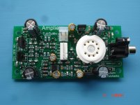
hey guess what? the first photos of the Greenamp V1.2 prototype boards 🙂
Now it's time for test!😉
I hope all goes well that is why I call it "prototype" 🙂 wish me luck I will inform if success or not success on the designNow it's time for test!😉
Vargas
oh by the way the logo is Oliver Queen from The Green Arrow since OS call the GreenampV1.2 I a made the logo from this image I know is silly I like super heroes till today 🙂 I attached the logo macro 😀
Vargas
Vargas
Attachments


- Home
- Amplifiers
- Solid State
- Slewmaster - CFA vs. VFA "Rumble"