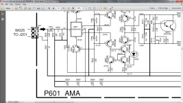
There was a discussion about a very similar sch, where it was agreed that the NFB should tap into the Signal Return and NOT into the Power Ground.Guy's, it is the kapton ND input stage with the 5 pair fet slewmaster.
View attachment 605521
That sch is now out of date following that agreement.
And that makes the post9735 sch wrong as well.
The recommendation for determining the NFB values is:
C2 >= sqrt(2) * C4 * R51 / R7 and for the values shown becomes enormous.
Turning around that recommendation to work back to a value for C4 one would use:
C4 <= C2 * R7 / R51 / sqrt(2) <= 1mF * 100r / 22k6 /1.4 <= 3.1uF
Maybe most of the designers are don't know Your calculation, because mamy commercial amplifier let the very low frequencies into the amplifier.
R54 still looks to be in the wrong location.
It is in the signal route and any interference current passing around the input circuit will develop an interference voltage across R54 that adds to the wanted signal.
Is this sch an original from the amp Designer, or has it been modified by some other Builder?
The location is OK for the R54, if You use it in integrated amplifier. It works against the local ground loop between the ground of the input stage, and the output stage. I did many fighting against it. And I got the solution from Marantz PM11s1, which use this resistor too.
I use this amp in dual mono configuration, so I don't need the common resistor to separate the signal ground from the power ground.
Sajti
Guy's, it is the kapton ND input stage with the 5 pair fet slewmaster.
View attachment 605521
The problem mentinoed by Andrew is not exist, as this amplifier has no DC blocking capacitor in the feedback route. The LF limit is 0.15Hz in the DC servo.
Sajti
Last edited:
And that makes the post9735 sch wrong as well.
Why are You judge without enough information?????
Sajti
There was a discussion about a very similar sch, where it was agreed that the NFB should tap into the Signal Return and NOT into the Power Ground.
That sch is now out of date following that agreement.
And that makes the post9735 sch wrong as well.
I don't think Ostripper changed the Kypton-ND Servo grounding. He did change the Kypton-V and Symasui. Those were the versions Thimios was seeing the strange servo behavior in. Here's a quote from Pete.
"I updated the servo schemes in those. Going with a much lower servo FB
impedance solves any slower settling times.
5.6K from TLxxx output to the NFB node gives <50mS settling and just
boosts global gain by a couple DB.
All the servo'ed creations ... (even my present leach/spooky) clone use
that 5.6k (DC) 22-27K (AC) feedback "mix". Nearly instant DC settling.
Edit - I have the V/symasui/spook - all reference the TLxxx (servo) to the signal ground
(lifted -4.7R). You might have the prototype versions - the PCB house versions are
the same (lifted servo reference).
OS"
I'm not sure about the schematic but the screen layout looks the same as the one that Thimios used and his Kapton nd worked fine as far as I know.
So, what is the final verdict. 10 uf or 2x 2.2uf in parallel for the input cap !😀
10uF is possible. Check my Marantz schematic 🙂
Sajti
Thanks guy's,
one last question. I have measured the 10uf poly cap and the esr is 0.02R. A normal electrolytic of 4.7uf is 2.6R. I suppose the lower the esr the better ?😕
one last question. I have measured the 10uf poly cap and the esr is 0.02R. A normal electrolytic of 4.7uf is 2.6R. I suppose the lower the esr the better ?😕
As built schematic.Guy's, it is the kapton ND input stage with the 5 pair fet slewmaster.
View attachment 605521
Attachments


- Home
- Amplifiers
- Solid State
- Slewmaster - CFA vs. VFA "Rumble"