I actually have a wood block the proper width for 1/4w.
Heck with through-hole for small signal !!
I'm sweating what packages will not frighten constructors.
1206 seems doable for resistors , SOT-26 and 23-6 also seem doable for
most dual matched pairs. You might even view the package ident. on these.
SOT-363 is too flippin' small.
MSAZ for zeners and TDK ceramics for all local decoupling.
That leaves non-smd for just the 22uf shunt caps and the final VAS
TO-126's.
75mm X <40mm IPS's will be the norm. Just plug em' in with those
cool euro-connects.
OS
I've been building up a supply of 0805 resistors and caps. I've found them to be handy for adding values to the bottom of a board. I have a few 1206 caps in 0.1uF for decoupling electros. I also have some stock of BC846/56 and some diodes. What I don't like are the vas transistors and electrolytics in surface mount. Too hard to hand solder for me. I know most guys would rather order boards so two sided is not an issue. I used to prefer them too, but afterwhile you start getting a pile of leftover pcbs not to mention, the time waiting on the slow boat from China. I just find I enjoy the diy aspect more if I etch the boards myself.
Blessings, Terry
I'm actually planning for the double sided pre-fabs'.
And WILL keep the "big" stuff (VAS + electro's) through-hole.
SMD electro's are too expensive , anyways.
I just want to get a full stereo pair on one 75 X 98mm typical
original slew IPS.
For your leftover PCB's , there is a whole group on the forum that
would rather have their amp's fully built - pass em' on.
OS
I'm actually planning for the double sided pre-fabs'.
And WILL keep the "big" stuff (VAS + electro's) through-hole.
SMD electro's are too expensive , anyways.
I just want to get a full stereo pair on one 75 X 98mm typical
original slew IPS.
For your leftover PCB's , there is a whole group on the forum that
would rather have their amp's fully built - pass em' on.
OS
I need to find those guys. My pile of built and tested amps is obscene.
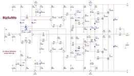
Ostripper i have a doubt regarding the Kypton V2 that I want to run it at lower voltage for ips and ops so I see the sound quality variation when I increase the voltage to 50 which is better than at 15V so what are the resistor values to be changed to get as good quality as at 50V
If you see the Bipsumo circuit then its observed that R8 R9 R10 R11 are different than what you are using.
So changing these values will give enough sound quality improvement?
If you see the Bipsumo circuit then its observed that R8 R9 R10 R11 are different than what you are using.
So changing these values will give enough sound quality improvement?
Attachments
Ostripper i have a doubt regarding the Kypton V2 that I want to run it at lower voltage for ips and ops so I see the sound quality variation when I increase the voltage to 50 which is better than at 15V so what are the resistor values to be changed to get as good quality as at 50V
If you see the Bipsumo circuit then its observed that R8 R9 R10 R11 are different than what you are using.
So changing these values will give enough sound quality improvement?
The one you're showing here is an early prototype 😉
Now I'm using R8, R9, R20, R21 = 100R.
More degeneration - more stability.
OS: Where is the latest version of SNOOPY IPS and OPS since last year on this forum. I have the boards just need to order parts and need to know the changes if any. Thanks, Ray Hughes
I'm presently making Spooky and the new groner IPS in a ultra small SMD
form with dual devices. You might want to wait.
The Slew IPS's will be @ 40mm and use those fancy euro quick
connect for the OPS/IPS interface. You won't have to mount the IPS to
anything.
Edit - oh you have the boards .... the same -except the servo feedback resistor
is 5.6K. This jumps the global gain by 2 db and makes the spook's DC settle in millisecond's.
OS
Last edited:
Sounds interesting. I really like my spookys, so I guess I have to build them. What does "those fancy euro quick connect" look like?
Are you also making the Groner IPS så the connectors fit to a standard OPS board?I'm presently making Spooky and the new groner IPS in a ultra small SMD
form with dual devices. You might want to wait.
The Slew IPS's will be @ 40mm and use those fancy euro quick
connect for the OPS/IPS interface. You won't have to mount the IPS to
anything.
Edit - oh you have the boards .... the same -except the servo feedback resistor
is 5.6K. This jumps the global gain by 2 db and makes the spook's DC settle in millisecond's.
OS
I must have photon phobia... I run away at the sight of a LED in the main signal path. Even standard diodes in the signal path make me feel "dirty"... dirty...dirty...dirty...
-----
Is anyone designing a super-duper output PCB with interleaved NPN-PNP outputs... larger power capacitors... etc.. Maybe for 4-pairs of M1 Sankens?
-----
Is anyone designing a super-duper output PCB with interleaved NPN-PNP outputs... larger power capacitors... etc.. Maybe for 4-pairs of M1 Sankens?
I have a situation in kypton V2 that the problem is when i increase the voltage using a dimmerstat initially both the led1 and 2 will glow but after increasing to full voltage of 50V only one will glow what is the problem here and its observed in almost 4 boards i made.The one you're showing here is an early prototype 😉
Now I'm using R8, R9, R20, R21 = 100R.
More degeneration - more stability.
Hello guys.
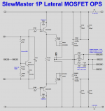
I work for MINI OPS LATERAL MOSFET.Q104/BD139/ to be mounted on a heatsink with 2SK and 2SJ??
Thanks
I work for MINI OPS LATERAL MOSFET.Q104/BD139/ to be mounted on a heatsink with 2SK and 2SJ??
Thanks
Attachments

Last edited:
No,driver transistors will be mounted on his separate heatsinkHello guys.
I work for MINI OPS LATERAL MOSFET.Q104/BD139/ to be mounted on a heatsink with 2SK and 2SJ??
Thanks
Hello guys.
I work for MINI OPS LATERAL MOSFET.Q104/BD139/ to be mounted on a heatsink with 2SK and 2SJ??
Thanks
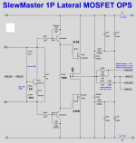
As Thimios said, and also you grabbed an older schematic. The values on the board are correct - follow those - especially for the gate stoppers.
To match each other.As Thimios said, and also you grabbed an older schematic. The values on the board are correct - follow those - especially for the gate stoppers.
Attachments
Last edited:
yes gate stopper resistors play a big role even in stabilization these laterals oscillate faster than you think.To match each other.
Any examples of the euro quick connectors? ANY possibility of integrating protection/control circuits in the new boards? Thanks for all the great work.😎I'm presently making Spooky and the new groner IPS in a ultra small SMD
form with dual devices. You might want to wait.
The Slew IPS's will be @ 40mm and use those fancy euro quick
connect for the OPS/IPS interface. You won't have to mount the IPS to
anything.
Edit - oh you have the boards .... the same -except the servo feedback resistor
is 5.6K. This jumps the global gain by 2 db and makes the spook's DC settle in millisecond's.
OS
How about the same with FETsIs anyone designing a super-duper output PCB with interleaved NPN-PNP outputs... larger power capacitors... etc.. Maybe for 4-pairs of M1 Sankens?
Has anyone run a single output pair mosfet mini-slew and checked what the operating temperature is? How much smaller is it possible to make that mini-slew with smd device where they can be used, obviously not the output devices themselves? How close in size can we come to Lazy Cats First One amplifier with this type of construction? Single board no Euro connectors both sections? Lazy Cat recommends running his design at 57C 135F and I'm wondering if that is really necessary with Mosfet devices to run that hot for best sound?
- Home
- Amplifiers
- Solid State
- Slewmaster - CFA vs. VFA "Rumble"