Of course , how else would I see it built (you + Thimios) ??
My problem is the 1381/3503's .... they won't be around much longer.
I have run one of these IPS's with a pair of mpsa92/42's at 3ma. 200mw
dissipation is no issue with an EF3. So , SMD would work here.
OS
whats wrong with the 1381/3503? why don`t they be available?
When ON acquires fairchild , many of beloved devices will go the way of
the many (through - hole) FET's that are so sought over on the forum.
Let's beat em' to the punch.
PS - look at how many are being manufactured , Fairchild is only belting
out a thousand at a time. Compare this with the 20K runs for most BF/MJD
SMD's.
The through-holes just don't bring back the $$ !
OS
I think SMD parts make for a quieter amp. The traces can be so short when you are stacking parts on both sides of the board, it doesn't leave any room to pick up noise.
Yes, probably true. I have been beginning to use more smd parts on the foil side for the small caps. However for the DIY enjoyment of etching and building, double sided layouts are a pain. So are SMD electros. For the few who like buying boards from the board house SMD makes a lot of sense. Thankfully, guys like OS and Apex have still been providing stuff for us etchers to build and have fun with.
I think SMD parts make for a quieter amp. The traces can be so short when you are stacking parts on both sides of the board, it doesn't leave any room to pick up noise.
And , most of my designs are super low current. Even 1/8w will do.
Those through hole 1/8'ths on the protection board were a PITA.
It really would be easier even to use 1206 SMD and a toothpick then
bending all those leads and reading all those stupid colors !
Your right .... those 22R's on a spooky amp could just crossover some
BC847/857's collectors (SOT-363) and fit into a little over a square CM .
The only through holes would be the electro's and VAS pair.
Toothpick and fine tip would actually be easier than those leads -
NO clipping .... Yeahhhh!
OS
Yes, probably true. I have been beginning to use more smd parts on the foil side for the small caps. However for the DIY enjoyment of etching and building, double sided layouts are a pain. So are SMD electros. For the few who like buying boards from the board house SMD makes a lot of sense. Thankfully, guys like OS and Apex have still been providing stuff for us etchers to build and have fun with.
You should have no issue home etching a 363/1206 SMD creation.
My preliminary estimate is that it would take just 1 side to make a
75 X 50mm SMD spooky.
OS
You need a good pair of needle nose pliers. They're the best lead bending jig you'll ever find if you figure out how to use them. I'll post a picture of what I mean tomorrow when I'm back at the office. 1/8W is easy.
I went away from the 1/8 watt parts on that earlier protection board and went back to 1/4W. The next version won't have half the parts the old one did. I'm moving everything off board onto data buses. We're preparing to go web interface. Check your temp or current draw from a web browser or smart phone. I also want to datalog, so I can see what is happening to the amp prior to shutdown. It would help diagnosing a failure.
I went away from the 1/8 watt parts on that earlier protection board and went back to 1/4W. The next version won't have half the parts the old one did. I'm moving everything off board onto data buses. We're preparing to go web interface. Check your temp or current draw from a web browser or smart phone. I also want to datalog, so I can see what is happening to the amp prior to shutdown. It would help diagnosing a failure.
When ON acquires fairchild , many of beloved devices will go the way of
the many (through - hole) FET's that are so sought over on the forum.
Let's beat em' to the punch.
PS - look at how many are being manufactured , Fairchild is only belting
out a thousand at a time. Compare this with the 20K runs for most BF/MJD
SMD's.
The through-holes just don't bring back the $$ !
OS
Agreed on one side but there is no official declaration about these parts are being discontinued. I think the parts might be surviving as many audio companies use these i believe.
But do we have smd equivalents for these? I mean as good as the 1381 / 3503
Yes, I'm cool with SMD as long as it is single sided and uses through hole electrolytics.
Blessings, Terry
Blessings, Terry
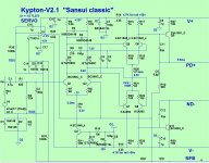
Is beta matching required for the transistors Q5, Q6, Q7, Q8 in kypton v2?
If not required then I want to go with smd version of 1845/992.
There is one more problem im observing with the kypton V2. That is when building a multi channel amplifier i found that the resistor R30 value 100ohm is burning. The voltage across is increasing quite high even after increasing the R21 to 820ohms. In other channels even with R21 being 100 to 150 ohms its working fine.
why that specific resistor is burning and giving fumes.
Think about it , all the other channels work. Either Q8/10 or the OPS is
suspect.
Swap a working IPS to that channels OPS , see if it's r30 burns ??
OS
Think about it , all the other channels work. Either Q8/10 or the OPS is
suspect.
Swap a working IPS to that channels OPS , see if it's r30 burns ??
OS
Q10? i couldnt see Q10 in above circuit.
I tried swapping the OPS its the same problem.
You need a good pair of needle nose pliers. They're the best lead bending jig you'll ever find if you figure out how to use them. I'll post a picture of what I mean tomorrow when I'm back at the office. 1/8W is easy.
I went away from the 1/8 watt parts on that earlier protection board and went back to 1/4W. The next version won't have half the parts the old one did. I'm moving everything off board onto data buses. We're preparing to go web interface. Check your temp or current draw from a web browser or smart phone. I also want to datalog, so I can see what is happening to the amp prior to shutdown. It would help diagnosing a failure.
Ahh , that's like a "smart fridge" or other useless "internet of things" type thing.
I would try it , but to keep just the basic analog protect with micro "embellishment"
is essential.
I do like the idea of the I2L bus. I fully intend to add it and at least the DC
onboard on my spooky all-in-one.
Yeah , 1/8 is easy ... but you still have to put the stupid lead through the holes
and clip them.
PS- a web/mobile interface is cool ..... but could be a bit "geeky" to some.
The circuit should be good enough not to need monitoring. 😀
OS
Q10? i couldnt see Q10 in above circuit.
I tried swapping the OPS its the same problem.
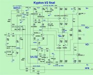
Q12 in that one. I dropped the superpair in V2.
(Q10 below) is "V2".
This is the one thimios tested.
OS
Attachments
You need a good pair of needle nose pliers. They're the best lead bending jig you'll ever find if you figure out how to use them. I'll post a picture of what I mean tomorrow when I'm back at the office. 1/8W is easy.
Here's the easy way to bend resistor leads neatly. If you need wider leed spacing, just move into the plier jaws farther. Once you figure out the magic spot on the needle nose pliers, the leads will fit perfect every time.
Attachments

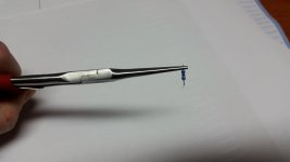
Here's the easy way to bend resistor leads neatly. If you need wider leed spacing, just move into the plier jaws farther. Once you figure out the magic spot on the needle nose pliers, the leads will fit perfect every time.
That's what I always do, but using tweezers 🙂
Here's the easy way to bend resistor leads neatly. If you need wider leed spacing, just move into the plier jaws farther. Once you figure out the magic spot on the needle nose pliers, the leads will fit perfect every time.
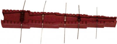
I actually have a wood block the proper width for 1/4w.
Heck with through-hole for small signal !!
I'm sweating what packages will not frighten constructors.
1206 seems doable for resistors , SOT-26 and 23-6 also seem doable for
most dual matched pairs. You might even view the package ident. on these.
SOT-363 is too flippin' small.
MSAZ for zeners and TDK ceramics for all local decoupling.
That leaves non-smd for just the 22uf shunt caps and the final VAS
TO-126's.
75mm X <40mm IPS's will be the norm. Just plug em' in with those
cool euro-connects.
OS
Maybe someone could put together a "practice" amp board😀 and do the cheap 10 by 10 boards from China...
Last edited:
- Home
- Amplifiers
- Solid State
- Slewmaster - CFA vs. VFA "Rumble"