It's a high power amp so you need big sinks,I personaly would leave them together.I look into the matter and see what's available for connection.
I designed all 3 OPS to fit a cheap "heatsink USA" 250mm x 100-125mm
HS.
With this arrangement the 90 degree PCB setup would be ideal.
OS
A 2nd way ...
This is also a valid way.
But , long standoffs would be required as the caps/heatsinks
would be facing each other.
Anyone using a large driver heatsink would need
real long standoffs/pins at the interface. 😕
Let's have some input .. here !!
EDit - I just thought ... mirroring the IPS would have it's component facing away from
the OPS. Still , this would not allow a very large driver heatsink .... just some
thoughts.
PS - with a non- mirrored board for IPS , the below arrangement could work with long
pins or standoffs. Not mirroring the IPS would allow for both arrangements.
I definitely want the first one (last post.).
OS
Attachments
Last edited:
Os,
In my application I have almost 16" of heatsink length with this as the vertical dimension. I also have about 12" of clear area to the front of the enclosure. The 90 degree solution would work for me but then I also have to add a section for the active crossover so I am not sure if this would be an extension of the ips section or if I would put the XO under the ips section and bring that back towards the output section. If I make the ips and xo one board I will add a shelf to hold the entire assembly so it is not hanging in free air. Basically another aluminum plate attached to the heat sink at a 90 degree angle. I will have to look at the width that I have, that will be the limitation. The plan for me is to have the entire assembly attached to the heatsink, that will be installed as an assembly into the enclosure. I will have to make a separate assembly for the power supply that will be attached as a stand alone unit.
In my application I have almost 16" of heatsink length with this as the vertical dimension. I also have about 12" of clear area to the front of the enclosure. The 90 degree solution would work for me but then I also have to add a section for the active crossover so I am not sure if this would be an extension of the ips section or if I would put the XO under the ips section and bring that back towards the output section. If I make the ips and xo one board I will add a shelf to hold the entire assembly so it is not hanging in free air. Basically another aluminum plate attached to the heat sink at a 90 degree angle. I will have to look at the width that I have, that will be the limitation. The plan for me is to have the entire assembly attached to the heatsink, that will be installed as an assembly into the enclosure. I will have to make a separate assembly for the power supply that will be attached as a stand alone unit.
Last edited:

Just an idea but ...
Using 1206 surface mount parts on the IPS board mounted at right angle would be space efficient and lend itself to short paths from the outside world.
Using 1206 surface mount parts on the IPS board mounted at right angle would be space efficient and lend itself to short paths from the outside world.
Os,
Is it really that important to have very short leads from the ips input to the connectors on the enclosure? We are only talking about a few inches, even let's say 6" of lead wire back to the connector. How is that different than having a meter of cable connecting a pre to the amp input?
Is it really that important to have very short leads from the ips input to the connectors on the enclosure? We are only talking about a few inches, even let's say 6" of lead wire back to the connector. How is that different than having a meter of cable connecting a pre to the amp input?
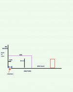
This would be the most secure way
If you like that way ... let me explain.
-It would allow a quad amp if someone had 16" (400mm) heatsinks.
- you could mount the IPS at the front panel (90 dg.) , as well.
- with the interface screwed in , just 2 standoff's could be used at
either front/back panel. To swap or remove IPS , just unscrew the
interface and the 2 standoffs.
-NFB can be a stiff wire "floating" above the driver heatsink. With a
tall driver heatsink , you could add a hole/rubber grommet and run
an insulated (18ga solid copper wire +UV reactive tubing)
through the driver heatsink to the IPS "NFB".
The UV cascode LEDS would highlight the "evil,alien" CFA return ..😀
That how I will do it ... it won't look like anything on the forum 🙂
PS - you will have to undo the mirrored IPS ... also the IPS just has
the wire wrap terminals. you could also use euroterms on BOTH IPS/
OPS and use right angle wire wrap terminals.
OS
Os,
Is it really that important to have very short leads from the ips input to the connectors on the enclosure? We are only talking about a few inches, even let's say 6" of lead wire back to the connector. How is that different than having a meter of cable connecting a pre to the amp input?
VAS to a EF3 predriver input is best kept short.
It is higher Z than an amp input. About the same as if the nad's
diamond buffer did not have it's 47K resistor at the input filter 😱 !!
OS
Just an idea but ...
Using 1206 surface mount parts on the IPS board mounted at right angle would be space efficient and lend itself to short paths from the outside world.
Yes , this setup is perfect for IPS miniaturization. Low currents /
minimal large passives are on the IPS.
The OPS should , however ... remain through-hole (easy to source) !
OS
OPEN discussion of sourcing vs. layout.
To facilitate ease of construction , suggestions are welcome
as to - ANYTHING ! 🙂
-what to make heavy duty - like power connections , interface and
OP device pads ....
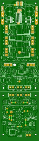
A lot of this layout is derived from the already debugged "Badger"
sourcing ... the big output pads , diode , inductors all fit. I had 2 revisions
to get it right (perfect). 😱
Below is the "combo" ...
comments welcome ...
OS
To facilitate ease of construction , suggestions are welcome
as to - ANYTHING ! 🙂
-what to make heavy duty - like power connections , interface and
OP device pads ....
A lot of this layout is derived from the already debugged "Badger"
sourcing ... the big output pads , diode , inductors all fit. I had 2 revisions
to get it right (perfect). 😱
Below is the "combo" ...
comments welcome ...
OS
Attachments
OS, I like the idea of laying out the IPS with 1206 SMT parts. This would reduce the length considerably.
When I build an amp I almost always mount the board flat against the heatsink. If the IPS were mounted at right angles then it might obstruct whatever is next to it - transformer, filter caps, soft start board, etc.
When I build an amp I almost always mount the board flat against the heatsink. If the IPS were mounted at right angles then it might obstruct whatever is next to it - transformer, filter caps, soft start board, etc.
OS, I like the idea of laying out the IPS with 1206 SMT parts. This would reduce the length considerably.
When I build an amp I almost always mount the board flat against the heatsink. If the IPS were mounted at right angles then it might obstruct whatever is next to it - transformer, filter caps, soft start board, etc.
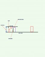
.... unless the IPS was at the front or back of the case
(or both , if you wanted a quad amp 😀 )
Weighing out the advantages AND the drawbacks of this design ....
Disadvantages ...
a. 2 boards + a interface.
b. 2 mounting surfaces ... the back (or) front panel and the heatsink.
c. possibly a more difficult build (more screws and mounting considerations).
Advantages -
a. Modular - easy upgrade path.
b. 4 amps in one case with either 4 "baby" / or master OPS ...front and back
panels used for the IPS's.
c. total separation of the "dirty" high current circuit from the sensitive
IPS.
d . Back panel mounting for IPS will have just a few CM input path while
the OPS will still be flat against the heatsink .. allowing for PS "embellishment".
OS
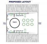
Proposed layout ...
(below) is how it will look.
The representation is roughly scaled to (2) heatsink USA
250mm X 100 (or) 132mm extrusions.
Hope this answers any questions.
PS - trafo would best be near the front (less stray field - IPS) +
better amp weight distribution. HK990 's trafo's are both near the front.
OS
(below) is how it will look.
The representation is roughly scaled to (2) heatsink USA
250mm X 100 (or) 132mm extrusions.
Hope this answers any questions.
PS - trafo would best be near the front (less stray field - IPS) +
better amp weight distribution. HK990 's trafo's are both near the front.
OS
Attachments
Last edited:
Another idea would be to put the transformers and some of the filter caps in a separate chassis. This way you could "plug in" different amps for development/ comparison and also keep the transformer noise away from the input....many other (cost) advantages......😀
Another idea would be to put the transformers and some of the filter caps in a separate chassis. This way you could "plug in" different amps for development/ comparison and also keep the transformer noise away from the input....many other (cost) advantages......😀
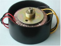
Steel covers (below) ....
for 400-500VA
AS-4450 - 400VA 50V Transformer - AnTek Products Corp
-dual mono is the way to go ... better than the HK990 "bare" setup.
OS
Attachments
Harry3,
What would you propose to use for the connector for your remote power supply? I am not going in that direction but just wondered what you would use to carry the 70V power to the amp module.
What would you propose to use for the connector for your remote power supply? I am not going in that direction but just wondered what you would use to carry the 70V power to the amp module.
OS, I think your idea is a good one. The RCA input connector could be placed directly above or below the IPS board, keeping wiring length to a minimum.
AC inlet and speaker out would go in the middle of the back panel, as far away from the IPS circuitry as possible?
People that don't like the screw connectors between the IPS and OPS boards can always solder short lengths of wire instead.
AC inlet and speaker out would go in the middle of the back panel, as far away from the IPS circuitry as possible?
People that don't like the screw connectors between the IPS and OPS boards can always solder short lengths of wire instead.
OS, I think your idea is a good one. The RCA input connector could be placed directly above or below the IPS board, keeping wiring length to a minimum.
AC inlet and speaker out would go in the middle of the back panel, as far away from the IPS circuitry as possible?
People that don't like the screw connectors between the IPS and OPS boards can always solder short lengths of wire instead.
Of course , after these modular' s are tested by party , "golden ears" , and
the "anally" inclined ... the best ones can be made into 200mm X 75mm
unified PCB's.
OS
- Home
- Amplifiers
- Solid State
- Slewmaster - CFA vs. VFA "Rumble"