This will be the combo I'm gonna offer
Hey , nice ...
Can you do the through- hole DL pads for the OP's , fuses , and
PS/ground/output connectors ? (another smaller pad on top - through holed)..
makes it easier to mount the OP devices , we did this one the "badger".
Also, maybe even the IPS/OPS interfaces (in case one want to
use "pins" for the IPS interface) ... or OPS interface.
OS
I imagine once we settle on the input section that we want to run we are better off with a soldered connection between the sections than any type of connector that can lose contact or become dirty over time?
I imagine once we settle on the input section that we want to run we are better off with a soldered connection between the sections than any type of connector that can lose contact or become dirty over time?
No issue here.
I ran my first badger as a module with wire wrap pins
into euroterminals for over 3 years , all was tight and
good.
IPS's have very low currents , as well (18ma max for the wolverine)
This would present NO problem for a euroterminal that can handle
AMP's !!
Bottom line .. a quality euroterminal properly tightened will
last for many decades. Military uses them ...
OS
Do you want a way to click the boards together?
They optimally go at a 90 degree angle to each other.
With the IPS along the back panel of the enclosure.
This way the input jack can be just CM's away from the IPS.
PS - for those with long heatsinks ... just leave the board together and jumper
the interface.
OS
Meanman,
Those types of standoffs are pretty easy to come by at least here in the US. I can't see how they attached the lower portion to the vertical board? An angle perhaps?
Those types of standoffs are pretty easy to come by at least here in the US. I can't see how they attached the lower portion to the vertical board? An angle perhaps?
OS,
The Euto connector you are talking about are screw down connectors? I just don't know them, I may have seen them in other equipment but never heard that term before. Something used in DIN chassis I would think, something I would have seen in perhaps a PLC enclosure?
The Euto connector you are talking about are screw down connectors? I just don't know them, I may have seen them in other equipment but never heard that term before. Something used in DIN chassis I would think, something I would have seen in perhaps a PLC enclosure?
OS,
The Euto connector you are talking about are screw down connectors? I just don't know them, I may have seen them in other equipment but never heard that term before. Something used in DIN chassis I would think, something I would have seen in perhaps a PLC enclosure?
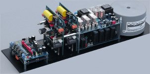
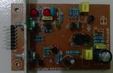
here is a pix of the very first "badger" , it
has the pins/euroterminal as interface.
This amp "partied" HARD for 3 years +. 😀
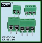
PS - pix of a standard euro terminal is #2.
OS
Attachments
Last edited:
Got it. I have wired plenty of those in DIN equipped wire runs. No problem just never heard the term before.
Got it. I have wired plenty of those in DIN equipped wire runs. No problem just never heard the term before.
Google "PCB euroterminal/block" there are 1000's of choices .
OS
My problem with non-solder connections is that circuits just aren't designed to have an internal connection open up during operation. It only needs to happen ONCE... That's why I don't use breadboards. These are high power amps, they will be used near speakers and depending on individual mounting methods will probably vibrate at certain notes. It's really not hard to solder a few connections after verifying everything works. After all, you've just soldered a whole PCB.
My problem with non-solder connections is that circuits just aren't designed to have an internal connection open up during operation. It only needs to happen ONCE... That's why I don't use breadboards. These are high power amps, they will be used near speakers and depending on individual mounting methods will probably vibrate at certain notes. It's really not hard to solder a few connections after verifying everything works. After all, you've just soldered a whole PCB.
That pix I showed , keen ... I had that amp on top of the speakers
(for 3 years) !
Those euro- terms were tight as hell after 3 years.
I would expect the chassis screws to loosen before the interface screws !
PS - I want to get "still4given" into this camp ... he will build every front
end on the forum ...as I "POP" EM' OUT !!
OS
Last edited:
Thanks ostripper so .....Q5=2SC1845,Q6=2SA970Q5/6 need the higher voltage.
Q7/8 can be 1015/1815 or any low voltage- high gain pair.
Q9/10 -cascode pair,,, need to be very high voltage (bigger I , as well)
... that is the reason for TO-126 mje340/350 or equiv.
OS
Q7=2SA1015,Q8=2SC1815 OR 1845
Q9=KSA1381E ,Q10=KSC3503E
Seems to be ok.
They optimally go at a 90 degree angle to each other.
With the IPS along the back panel of the enclosure.
This way the input jack can be just CM's away from the IPS.
PS - for those with long heatsinks ... just leave the board together and jumper
the interface.
OS
It's a high power amp so you need big sinks,I personaly would leave them together.I look into the matter and see what's available for connection.
My VFA IPS using Hawksford cascode VAS.
I change resistor emitor on VAS to 100 Ohm, reduce VAS current almost same as my CFA's VAS current.
I almost can not notice the different in listening test of my CFA and VFA. But female voice like "tsss" or "tttzzzz" is more nice on my CFA. Different slew rate or different harmonic pattern?
I realize that I must compromise the VAS linearity before adding feedback and maximum open loop gain to get "nice sound".
Attachments
Consider your inquisition into symmetry, add a bridge, then take a Pass at it. Might be surprised. CFA, VFA, either one will work. I woul imagine it would look like what MIB was hinting at. I had a thought about the possiblilty of an UGS stage and HAwksford Vas, if it is as superior as you say.I never understood why this topology has many fans ... now I know.
ALL this fuss about CFA superiority .... could it be just a case of
symmetry ?
First of all , this is a lowly VFA amp ..... not enough slew , but high
PSRR. So why do I get 200V/uS here ? Back to symmetry. The loop gain
plot is nearly identical to the CFA's (below 1) ... why ? As is a very high
gain margin at 20Khz , also like the CFA. 1.25mhz UG point , too .
PSRR is between a "blameless" and a CFA ... more like the current sourced
VSSA , but flatter (lower)- way down into LF ... (below 2).
Distortion is second only to the "blameless" (more like a VFA here - below 3).
I suspect this is why harmon/Kardon chose this as their top-of-the- line
receiver amp topology - this amp seems to combine the best traits of
both CFA AND VFA 😱 .
(below 3) at a 3R load at 2/3 power , it "smokes" all the other amps
, especially from 10HZ ! to 25K (7-15ppm) .. 🙂
PS - Professor leach added lead compensation to NFB to allow more
UG margin at a higher frequency ... use 2.7- 3.9p at the "LC" pads
on PCB ... Be sure to look over the package real well - print it out ...
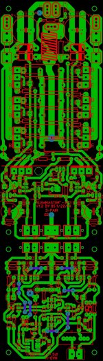
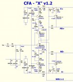
Compare to schema ... (It's a 1.1 version) 😀
ENJOY !
OS
- Home
- Amplifiers
- Solid State
- Slewmaster - CFA vs. VFA "Rumble"