I replaced r23 and r24 with 2k7 ohms and now I got the red leds to light up and adjusted for 3.8V across r12 and r13.
Between pd+ and pd- I measure 12.8v.
I tried to connect the ips to the ops still using the bulb limiter. The light bulb started glowing and the rails dropped to 24v.
I tried powering it up without the bulb limiter but the bias shot up to 150mv and could not be adjusted.
I tried to play some music through it (I don't have a scope) and it sounded very distorted, so I shut it down and plugged in the bulb limiter again for further testing.
Any ideas?
If there's any sign of trouble, it's a bad idea to remove the bulb limiter. 12.8V is pretty high across PD+ and ND-. Are you getting a steady 12V at the zeners now?
I'm getting 12.04 and 12.09v across the zeners.
Should the red leds light up bright? My are just glowing.
Should the red leds light up bright? My are just glowing.
The leds will just be glowing. They don't usually turn on full blast until there is 15mA flowing through them. They just need to drop 1.7V.
It's probably easiest if you mark up a schematic with all the voltage drops and some voltage readings to ground for the VAS section.
It's probably easiest if you mark up a schematic with all the voltage drops and some voltage readings to ground for the VAS section.
OK, so your shunt regulators are up and running and are adjustable which is good.
What do you measure over the 150Rs R25 and R31? Calculate the total VAS current from your readings. Should be in the neighbourhood of 7.5mA.
What do you measure over the 150Rs R25 and R31? Calculate the total VAS current from your readings. Should be in the neighbourhood of 7.5mA.
Yes, 8mA for the VAS and Hawksford cascode, which is about right. Your IPS may well be OK and the issue may be with the OPS instead. I'll be off-line for the balance of the day but maybe jwilhelm or others may be able to join in too.
I guess the OPS is the place to start troubleshooting since everything seems to work fine until +pd and -nd is connected to the OPS.
Seems like the ops got problems. The rails fall from 54v to 24v when I insert the 15k resistors between + and PD, and - to ND.
Try turning the bias pot while you have it hooked up with the light bulb. You should be able to get the light to go out.
With the bias pot on maximum resistance and 15k resistors installed, the bulb gets a little bit brighter and the rail voltage falls to around 25v.
When I increase the bias, the bulb gets brighter and the bias adjustment seems to work fine.
I noticed that in the schematics Q105 should be mje340 and Q106 mje350. I populated these with 2sc3503 and 2sa1381 according to a BOM I found somewhere in this thread.
Should I replace these with MJE340 and 350?
MJE340 and 2SC3503 are NPN
MJE350 and 2SA1381 are PNP.
Make sure you used the right ones.
MJE350 and 2SA1381 are PNP.
Make sure you used the right ones.
Last edited:
Either you are mistaken on which way maximum resistance is on the pot or Q103 and Q104 aren't doing their job. Raising the pot resistance should raise the current available to the bases of those two transistors, which should make them conduct more. The more they conduct, the less current there is available to the predrivers and the rest of the output stage.
You should verify you are correct on the bias pot adjustment. Put an ohm meter on the two pot leads that aren't shorted by the board trace. It should read 200 ohms. If you have 200 ohms there, power the board up again and measure the voltage between the base and emitter on both Q103 and Q104. If they are functioning properly there should be around .6 volts present.
You should verify you are correct on the bias pot adjustment. Put an ohm meter on the two pot leads that aren't shorted by the board trace. It should read 200 ohms. If you have 200 ohms there, power the board up again and measure the voltage between the base and emitter on both Q103 and Q104. If they are functioning properly there should be around .6 volts present.
2SC3505 for Q105 and 2SA1381 for Q106 are actually a better choice than MJE340/350. They are faster devices.
With bias pot on 200r I measure 0.6v across base and emitter on q103 and q104. I have 0.6v between b and e on all transistors including outputs.
The rails are now 37v with 15k resistors from v- to ND and v+ to PD and the bias pot at 300r.
Voltage across one 0.22r resistor is 5-6mv.
When removing the resistors the rails increase to 53v and I get 0-0.1 mv across the 0.22r.
I'm using a 60w light bulb for testing, does it limit the current too much? 240v mains.
It sounds like you do have issues with the output board. The output devices shouldn't be conducting with the pot at 200 ohms. Can you post a few good pictures of the board? The issue will be at the input end.
A 60 watt bulb is fine. I use 50 watts normally, but switch to a 100 watt bulb if I want to run a lightly loaded amp that is giving me problems.
You said you have voltage across one of the emitter resistors only? Do you have all pairs installed?
I have voltage across all of the emitter resistors. All pairs installed.
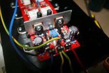
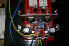
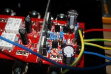
Here's some pictures:
Here's some pictures:
Attachments
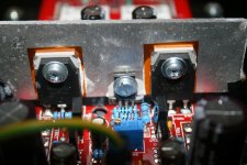
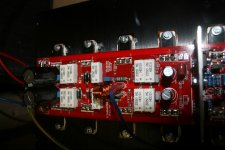
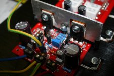
The pictures seem to all blur around the resistors I can't quite see them. Is D102 shorted? It should be.
- Home
- Amplifiers
- Solid State
- Slewmaster - CFA vs. VFA "Rumble"