We want pure hi-fi amplifiers ,no PC not Servers.
That was the issue with the Arduino protection by "purist's" , as well.
"NO Voodoo in my amp" 🙄 .
OS
We want pure hi-fi amplifiers ,no PC not Servers.
The network connection actually sounds pretty cool to me.😀
Last edited:
And easy to implement alsoThe network connection actually dounds pretty cool to me.😀
I am only using one pair of output transistors for slewops with +-36V PSU and 8 ohm speakers.Everything is fine so far.Any chance for degraded performance due to the use of only one pair??
All my test is using one pair only.My power supply is +/-50V.I am only using one pair of output transistors for slewops with +-36V PSU and 8 ohm speakers.Everything is fine so far.Any chance for degraded performance due to the use of only one pair??
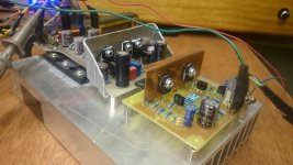
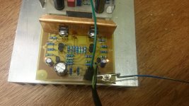
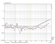
I got the symetri IPS up and running (a bitt differend values).
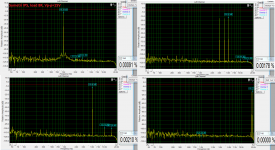
The bad news for bimo is that there is nothing to measure, the distortions are very low 😀
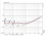
The distortion profile is changing with output power. Clipp is nice and soft, squares are nice, the VAS is running a bit low (9,2mA now), the LTP are at 3.7mA total. I will have to make a small adjustment and do some more tests.
Nice work bimo !!
The bad news for bimo is that there is nothing to measure, the distortions are very low 😀
The distortion profile is changing with output power. Clipp is nice and soft, squares are nice, the VAS is running a bit low (9,2mA now), the LTP are at 3.7mA total. I will have to make a small adjustment and do some more tests.
Nice work bimo !!
Attachments

Last edited:
Borys,
One question I have is why you chose to place the output device so close to the end of the extrusion? It would seem that would give the worst case situation of heat distribution between output devices.
One question I have is why you chose to place the output device so close to the end of the extrusion? It would seem that would give the worst case situation of heat distribution between output devices.
Borys,
One question I have is why you chose to place the output device so close to the end of the extrusion? It would seem that would give the worst case situation of heat distribution between output devices.
Do you not see the vertical fins ? An extrusion like that is different
than my horizontal ones.
It would stand on end , outputs would be at the bottom where the
convection starts. Ideal , actually (for that extrusion).
My 3 pair MT-200 sub amp is similar .
OS
OS,
Even in a vertical situation you would think the device closest to the edge would have a different dissipation than the other devices. I understand that the vertical fins would make it easier for the heat to rise, my speaker design is designed around a heat sink just like that, it just doesn't intuitively seem correct that way. I'd like to see what the actual measured heat distribution was on that heatsink in that configuration from bottom to top.
Even in a vertical situation you would think the device closest to the edge would have a different dissipation than the other devices. I understand that the vertical fins would make it easier for the heat to rise, my speaker design is designed around a heat sink just like that, it just doesn't intuitively seem correct that way. I'd like to see what the actual measured heat distribution was on that heatsink in that configuration from bottom to top.
Borys,
One question I have is why you chose to place the output device so close to the end of the extrusion? It would seem that would give the worst case situation of heat distribution between output devices.
This is only my test OPS for the lab work, laying flat on the bench all the time 😀 (heatsing gets really warm, good for testing bias stability)
Today I have shorted the output by mistake with some sine at the input applied and I was wondering why my I can hear some quite loud buzzing/hiss noise form the PSU. The toshiba outputs survived !! They are tough transistors.
Thanks Borys. You could answer my question nicely if you stand your sink on end and take some temperature measurements of the three devices as stacked if this was in a vertical position. That will be the configuration on the speakers I am working on. the sink fins run in the vertical axis and the entire sink is mounted vertically. I'm not sure that just measuring across the devices and looking at current loads would tell us much unless all three pairs are closely matched electrically?
OS,
Even in a vertical situation you would think the device closest to the edge would have a different dissipation than the other devices. I understand that the vertical fins would make it easier for the heat to rise, my speaker design is designed around a heat sink just like that, it just doesn't intuitively seem correct that way. I'd like to see what the actual measured heat distribution was on that heatsink in that configuration from bottom to top.
Nope , vertical works different. 3 devices also work different thermally
than 5.
Borys's would be ideal with
about 33-40% of the extrusion below
the 3 pair. I've measured the bottom of a 300mm vertical , >5C cooler on the bottom.
His first pair might be a Celsius cooler than his top 3'rd pair (with convection).
os
Thanks Borys. You could answer my question nicely if you stand your sink on end and take some temperature measurements of the three devices as stacked if this was in a vertical position. That will be the configuration on the speakers I am working on. the sink fins run in the vertical axis and the entire sink is mounted vertically. I'm not sure that just measuring across the devices and looking at current loads would tell us much unless all three pairs are closely matched electrically?
I will try to measure temperatures tomorrow and let you know.
OS,
So if you were running a 5 pairs slewmaster on a vertical heatsink don't you think that you would still want to space the output devices perhaps slightly shifted to the bottom like you have done on your new V3 boards? I wouldn't think just because you were using a vertical sink with vertical fins that would make it okay to stack all the outputs near the bottom of the sink. Perhaps optimum spacing would be different in reality than on a horizontal sink but I would think there would stll be better heat distribution with spaced devices, especially if the heatsink wasn't over-sized and dissipation was a real factor at high enough output.
So if you were running a 5 pairs slewmaster on a vertical heatsink don't you think that you would still want to space the output devices perhaps slightly shifted to the bottom like you have done on your new V3 boards? I wouldn't think just because you were using a vertical sink with vertical fins that would make it okay to stack all the outputs near the bottom of the sink. Perhaps optimum spacing would be different in reality than on a horizontal sink but I would think there would stll be better heat distribution with spaced devices, especially if the heatsink wasn't over-sized and dissipation was a real factor at high enough output.
OS,
So if you were running a 5 pairs slewmaster on a vertical heatsink don't you think that you would still want to space the output devices perhaps slightly shifted to the bottom like you have done on your new V3 boards? I wouldn't think just because you were using a vertical sink with vertical fins that would make it okay to stack all the outputs near the bottom of the sink. Perhaps optimum spacing would be different in reality than on a horizontal sink but I would think there would stll be better heat distribution with spaced devices, especially if the heatsink wasn't over-sized and dissipation was a real factor at high enough output.
You need a way to make the bottom device run as warm as the rest. if it's too far from the bottom it will run cooler and not carry it's load, causing it to run even cooler. Opposite of thermal runaway.
OS,
So if you were running a 5 pairs slewmaster on a vertical heatsink don't you think that you would still want to space the output devices perhaps slightly shifted to the bottom like you have done on your new V3 boards? I wouldn't think just because you were using a vertical sink with vertical fins that would make it okay to stack all the outputs near the bottom of the sink. Perhaps optimum spacing would be different in reality than on a horizontal sink but I would think there would stll be better heat distribution with spaced devices, especially if the heatsink wasn't over-sized and dissipation was a real factor at high enough output.
The V3 boards are optimized for a horizontal 3U to 5U.
I would say the V2 boards would be better for a Vertical extrusion.
Edit - with 3 pair double spaced. 5 pair ... maybe ??
My new amps are @40C across the top and 38C on the bottom at idle.
Absolutely perfect - end to end ! So on the V3 board , the PNP's are
2C warmer on one channel , NPN's 2C warmer on the other channel.
NFB takes care of this.
My vertical sub amp is different , P/N is the same. Slight 1C difference from
top to bottom. As JW said , as the vertical heats up - convection will
make the bottom cooler. Both are still much better than the 8C cooler
ends of my last horiz. (chinese) V2 extrusion.
OS
Last edited:
I got the symetri IPS up and running (a bitt differend values).
The bad news for bimo is that there is nothing to measure, the distortions are very low 😀
The distortion profile is changing with output power. Clipp is nice and soft, squares are nice, the VAS is running a bit low (9,2mA now), the LTP are at 3.7mA total. I will have to make a small adjustment and do some more tests.
Nice work bimo !!
Thank you for the measurement. I see D3 is dominant until 3kHz. I don't know this mean something.
What about listening test?
Okay,
I get it. Convection is going to change everything I guess.
Yes , that is another variable.
For DIY , the V2 vertical or the v3 horizontal is the best we can do
on this type layout.
Pass labs uses a inline P/N/P/N array down a propitiatory extrusion
using a long 450mm PCB with parallel rail tracks. Each device , either
P/N .... see's the same thermal conductivity.
Everything is a compromise.
OS
Thank you for the measurement. I see D3 is dominant until 3kHz. I don't know this mean something.
What about listening test?
Bimo , Borys's setup might give accurate 1K results. >10K the sampling
rate of the hardware will not be as "fair".
An actual AP test of the "symetri" would likely be 1/3 the >10K thd.
OS
- Home
- Amplifiers
- Solid State
- Slewmaster - CFA vs. VFA "Rumble"