Carl,
I assume you are referencing the old Sumo amplifiers here? Great sounding amps. Nobody seems to have the actual schematics I have seen, I used these amps on loan from Sumo at a CES show, I loved those amps.
No, I am talking about ATI's new Signature Series of amplifiers. James Bongiorno (old friend and past employee of Morris Kessler) consulted on this design shortly before his death.
This page offers up some design detail ... http://www.wwsp.com/ati/at6000.htm
____________
Best Regards,
Carl Huff
Last edited:
Okay,
It was just that James was the designer of the Sumo line. So if he was part of this project I would think he would have brought that knowledge with him on this project. A very well respected designer.
It was just that James was the designer of the Sumo line. So if he was part of this project I would think he would have brought that knowledge with him on this project. A very well respected designer.
I would sat that feedback is applied to the backside of the symmetric Long-tail pairs in a fully traditional matter, the special part of the circuit is the VAS configuration, can be made even simpler and even better... 🙂
Hint- lunch break
Hint- lunch break
Last edited:
I would sat that feedback is applied to the backside of the symmetric Long-tail pairs in a fully traditional matter, the special part of the circuit is the VAS configuration
Yes , that is true. LTP (-) just shunts the "backside" of the VAS. Overload is
forcefully clamped ! As I said , this IPS could be overloaded continuously with
no stress.
LTP and VAS are "as one" in this design. Spook does NFB only in the LTP ,
VAS is controlled only be the (+) part of the tail.
OS
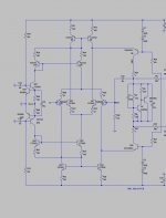
Is there something wrong with the way Q5 is drawn?
No , that is just the led reference "string" going through (and connecting) to Q5's base.
SUCH as simple circuit , but with real low THD (30ppm /20k/100v p-p).
Another difference -
120hz = .0011% , 60hz = .0007% and 20hz = .0002%
CFA's won't "bottom out" in the LF like this , spook tends to just stay at 20ppm
20-200hz.
Bottom line - this is a bass amp - for sure.
OS
This is an even simpler version. This is servo-ed, but could also be A/C coupled for those fancying that.
I really like that , but it is NOT simpler ?
OS
Oh yes,simpler, but in my version with current mirrors and advanced housekeeping the transistor count increases, it holds the same advantages as yours, but also a lot more... 🙂
Creative, simple and self balancing.
Creative, simple and self balancing.
Oh yes,simpler, but in my version with current mirrors and advanced housekeeping the transistor count increases, it holds the same advantages as yours, but also a lot more... 🙂
Creative, simple and self balancing.
Can I make an IPS out of it (not IP ?).
Call it the MiB IPS (alien edition). It is also so very different than the boring
standard LIN topology. No more boring IPS's ... leach , self - all "beat to death"
around here. 😀
OS
Cool ,just made it work in my mind ! TIS /folded cascode. This is the one type IPS
that I have not offered yet - perfect. 🙂
OS
that I have not offered yet - perfect. 🙂
OS
Okay,
It was just that James was the designer of the Sumo line. So if he was part of this project I would think he would have brought that knowledge with him on this project. A very well respected designer.
Yea, Jim knew his stuff. His latest company was Spread Spectrum where he brought back his Ampzilla amplifier of the 70's as the Ampzilla 2000. It was and still is a great product. Too bad we've lost him.
___________
Best Regards,
Carl Huff
Just sent the OPSv3 zip file to the board house. We will see what they come back with.
Many thanks, E
Many thanks, E
First steps of OPS board order have been taken. There should be enough to get started. I will let everyone know price and delivery date when I can.
Evan
Evan
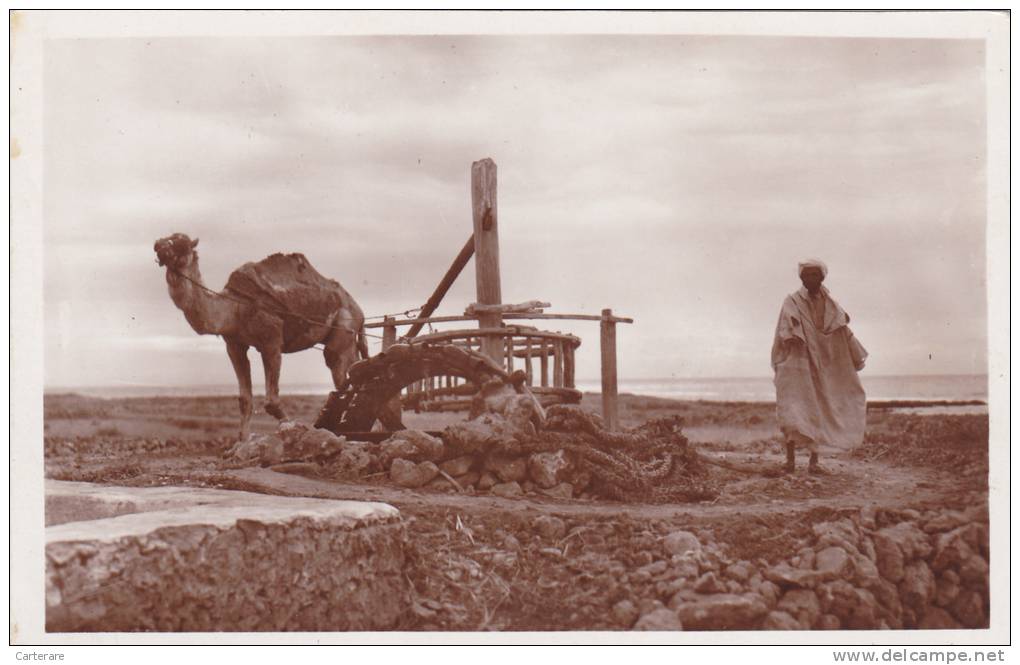
By esperado - That-s why your work is refreshing.
That is an original "old world" photo.
he must have heritage (roots). I am a child of war refugees ,
know nothing of heritage - to live multi-generational in one place ??😕
Would be interesting (many generations working the same land).
OS
First steps of OPS board order have been taken. There should be enough to get started. I will let everyone know price and delivery date when I can.
Evan
If JW's port from sprint 6 is good , truly a perfect board.
I did further thought on any effects having the first pair of outputs nestled in the
driver/ multiplier area ( below) might be.
I "magnified" any parasitic feedback , either capacitive or inductive.
(below 1 and 2) the worst case 500pf or a direct megaohm feedback
does nearly NOTHING to the multiplier outputs.
So , having the outputs here affect nothing ... even if you had a rosin flux
bridge or the tracks much closer. I doubt you would have even nano farad
capacitance at 4mm distance. Pushing a lot of current through these close outputs
also does not affect the multipliers with mutual inductance. You could even
lower the impedance of the multiplier dividers (if you were paranoid) 😀
EVERY thing is thought out for the PCB !
PS - A note .... for "arc welder" reasons , the rails and the output inductor should
not have input stages (or body parts) near it 😀 , A field will be emitted , but
the IPS should not be over the main section of the OPS regardless.
It should be perfect , Evan. You could even build it "sloppy" - has a huge error
factor for stability.
OS
Attachments
- Home
- Amplifiers
- Solid State
- Slewmaster - CFA vs. VFA "Rumble"