Thanks for inputs, i tried this:
Lifted q7 and q12 and replaced r20 +r21 with 1.2kohm, now i measured 1.5v around these resistors and 0.8V around r22+r27, offset is -5v but now i measure 15V between PD and ND.
2sc3503 and 2sa1381 replaced with 2sc3601 + 2sa1407.
As soon Q7 or q12 are placed in the circuit the voltage around r22 or R27 drop to almost zero V.
Nothing get warm and all transistors VBE looks fine.
Last edited:
It's kind of a balancing act to set the current I think. Setting R20/21 to 1.2K has gotten you higher VAS current by increasing base current on Q7/12 only. Q8/11 gain should likely be adjusted proportionally. I think it would be better to lower resistance in R22/27 to 47R, then lower R20/21. As your circuit is operating right now all your VAS current is coming from the bases of Q7/12 which isn't great. Try 680R for R20/21 to start.
This may sound very confusing because my terminology is terrible (Truck mechanic) but from looking at the superpair schematic it looks to me like R20/21 set the gain of the superpair and R22/27 set the actual current available to work with. Superpairs can be unstable (look at Kypton-V). Gain and available current are proportional to keep it stable.
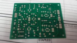
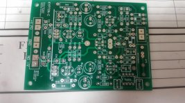
I have found more layout errors on the PCB, the input R1 + R2 + R3 + D1 +D2 are also shortened by R3 because of wrong tracks. I did a re arrange of these, id did not solve the main error, but I have now attached a picture of the top and Buttom PCB. (unused PCB without the fixes)
Can you please help me look all the traces and pads to see if you can found more errors?
Can you please help me look all the traces and pads to see if you can found more errors?
An externally hosted image should be here but it was not working when we last tested it.
An externally hosted image should be here but it was not working when we last tested it.
I have found more layout errors on the PCB, the input R1 + R2 + R3 + D1 +D2 are also shortened by R3 because of wrong tracks. I did a re arrange of these, id did not solve the main error, but I have now attached a picture of the top and Buttom PCB. (unused PCB without the fixes)
Can you please help me look all the traces and pads to see if you can found more errors?
An externally hosted image should be here but it was not working when we last tested it.
An externally hosted image should be here but it was not working when we last tested it.
Where is the wrong tracks for the input?
Please see attached picture, showing my modifications
The green arrow show where I moved the input track (topside) to
The red arrow show a new shortcut I made.
Blue arrow show a cut I made.
The green arrow show where I moved the input track (topside) to
The red arrow show a new shortcut I made.
Blue arrow show a cut I made.
An externally hosted image should be here but it was not working when we last tested it.
I think this is an error caused by the way I store my data files. I store everything on an online server and work from multiple computers. I think there is an issue with slow uploading of the files. I will stop working on a project and shut down my computer. Later I will start again from another computer. I think where the issue arises is when I restart the first computer it will finish uploading a previous file and undo work on me. This is likely why I'm having so many basic errors in my boards lately as well.
jwilhelm,
I'm not sure your explanation of what would corrupt your files is the use of multiple computers but one thing to do is each time you save a file you give it a unique file name. I do a lot of cad work and use more than one computer and move files back and forth, but each time I make a change I either store it as a copy of the original file or give it a new updated file name, that can be a file name or just add a revision # so you know your files are not being changed inadvertently. Now I hope you aren't saying the Krypton-C boards you made could be corrupted?
I'm not sure your explanation of what would corrupt your files is the use of multiple computers but one thing to do is each time you save a file you give it a unique file name. I do a lot of cad work and use more than one computer and move files back and forth, but each time I make a change I either store it as a copy of the original file or give it a new updated file name, that can be a file name or just add a revision # so you know your files are not being changed inadvertently. Now I hope you aren't saying the Krypton-C boards you made could be corrupted?
jwilhelm,
I'm not sure your explanation of what would corrupt your files is the use of multiple computers but one thing to do is each time you save a file you give it a unique file name. I do a lot of cad work and use more than one computer and move files back and forth, but each time I make a change I either store it as a copy of the original file or give it a new updated file name, that can be a file name or just add a revision # so you know your files are not being changed inadvertently. Now I hope you aren't saying the Krypton-C boards you made could be corrupted?
I've started doing the name changes recently when I noticed some odd traces showing up on other boards. I wish the files would corrupt so I would be aware there was an issue. The Kypton boards I sent to you are good other than the reversed D8 and the recent value changes.
Thanks, that comment made me wonder about those boards. Glad it is only a couple of known issues. I am planning on copying either your or OS's component part numbers so I think all should be well.
Thanks, that comment made me wonder about those boards. Glad it is only a couple of known issues. I am planning on copying either your or OS's component part numbers so I think all should be well.
OS's last schematic is good. You need to tune the output to your semi's and rail voltages though.
Here's a topside photo. Component locations have changed too.
Do you still has these boards for sale
Please let me know🙂
Thank you
Im done a hardwired version of OS amp, function rock stable.
No pictures?
R20 and 21 = 470R, R22 + R27 = 68R, r25 reduced to 20k. Measured about 50v around R25. I don't Think it do any change to raise r20+r21 as voltage are close to zero around r22 + R27 and base current IR23 and R26 are High as 2.6mA??
Thanks for your help🙂
R23 / 26 would only show any real current draw is if you had Q9/10 reversed.
In actual operation , even if you were running a 10ma VAS , R23/26 would
be uA - microamps (20-30uA).
The only current should flow through the LED's and the Q8-11 collectors/emitters.
the bases just need uA - even pA to run.
OS
- Home
- Amplifiers
- Solid State
- Slewmaster - CFA vs. VFA "Rumble"