Thanks Valery,
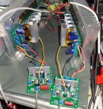
I've been wondering. A few years ago when I built my 6 pair Leach Low TIM, the boards were set up like these with a split in the rails between the front end and the back end. You could either install a jumper or you could run the front end at a higher rail. It was recommended to me to use a voltage doubler circuit to raise the voltage by about 5V or so. I built a circuit based on the PSU for the Pass A75. You can see that here. I had help of course so I don't exactly remember how the voltage was adjusted but it allowed me to use on transformer and get higher voltage for the front end. It works well and the Leach has been playing perfectly for 8 or 9 years now. I just built the regulator portion on a perfboard. Do you think that might be a good option here?
Thanks, Terry
If you're using a toroidal transformer can you just wrap a few extra windings onto it and series them on top of the main rails for the input rail voltage boost?
Thanks Valery,
I've been wondering. A few years ago when I built my 6 pair Leach Low TIM, the boards were set up like these with a split in the rails between the front end and the back end. You could either install a jumper or you could run the front end at a higher rail. It was recommended to me to use a voltage doubler circuit to raise the voltage by about 5V or so. I built a circuit based on the PSU for the Pass A75. You can see that here. I had help of course so I don't exactly remember how the voltage was adjusted but it allowed me to use on transformer and get higher voltage for the front end. It works well and the Leach has been playing perfectly for 8 or 9 years now. I just built the regulator portion on a perfboard. Do you think that might be a good option here?
Thanks, Terry
Hi Terry,
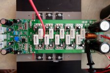
Makes sense. 5-6 volts above OPS supply will be good. In this case you need to remove the jumpers, marked by arrows on the picture, and connect your regulated rails to the left side of them respectively. I deliberately show the picture without the drivers - just to have a better view, they have to be there.
Just make sure, your regulated supply can deliver at least 100 mA of continuous current (better a bit more, just to be on a safe side) for each rail. Actual consumption will be around 40 mA for each rail (per channel, so multiply by 2).
Cheers,
Valery
Attachments
We would eliminate R114 and R115 as well, correct?
You can leave them - together with C110, C111, C112, C113 they just form an additional RC filter...
Cool. I'll have to try that. I may have to open up my Leach to refresh my memory.
Thanks, Terry
Thanks, Terry
I'd have thought the main point of the MOSFET amp would be to those who already have a stash of FETs stuck in a draw 😀
Some folks think they "sound" better. I'm going to try and test that theory soon. 😀
They are cheaper if you need to buy outputs. I happen to have a large stash of MJL's and NJW's so it cost me to try this, but if you're building from scratch and have to buy all your parts, the MOSFET build is definately cheaper. Less parts and cheaper devices. A DIY'ers dream. 😀
They are cheaper if you need to buy outputs. I happen to have a large stash of MJL's and NJW's so it cost me to try this, but if you're building from scratch and have to buy all your parts, the MOSFET build is definately cheaper. Less parts and cheaper devices. A DIY'ers dream. 😀
I don't really understand why something that is less linear would sound better unless the FETs have a better crossover region, but from I've read, I thought that they didn't. Oh well.
It will be interesting to hear (or read about!) your A/B comparisons Terry.
It will be interesting to hear (or read about!) your A/B comparisons Terry.
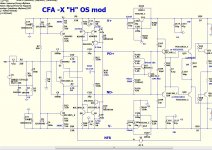
I was bored today so I sat down with my CFA-XH OS mod. This is the circuit that OS left with us a couple of days before he left. You can see it in post #3004. I built it and it didn't work so I sat it aside planning to deal with when he came back. Well who knows when that is going to happen so I thought I would post my findings in hopes that one of you might be able to shed some light on what might be causing it. I hooked up the IPS alone first and it plays nice. The output is a little higher than the others but didn't seem too bad. I usually see about +-1.7V on PD and ND and this puts out about +-2.1V. I played square waves through it and they look really nice. Now when I hook it up to the OPS, it surges. I turned the bias all the way down and used a light bulb. I am monitoring the bias and it stays very low so at least it's not trying to blow up. It will play a sine wave in between Oscillations. Any ideas what would cause the surging?
Thanks, Terry
Thanks, Terry
Attachments
Last edited:
My guess is C7 & 8 are slowing the inputs down and charging. I think they would make the feedback circuit sluggish.
If they were to improve PSSR they may be better connected on the rail side of R13 &14. Remember where this is coming from. Your guess is likely better than mine.
C7 and C8 are the feedback DC blocking capacitors. That FB arrangement has been shown to work. I suspect going back to normal Miller compensation will likely help.
If you're using a toroidal transformer can you just wrap a few extra windings onto it and series them on top of the main rails for the input rail voltage boost?
Yes just a few turns, make it twice for the 2 rails.
In my build I will make a trafo with boosted output +/-10 volts above the OPS rails for the IPS.
Last edited:
I'm afraid I don't know what the Miller compensation is. Looking a at this one, it is very close to what BV did except for a 1K resistor from PD/ND to the feedback loop and one extra 100p cap per side. However those are not in the original design.
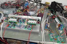
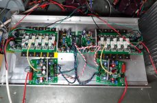
I took some time and set up the BJT OPS and MOSFET OPS side by side and hooked them up to my A/B setup. There are couple of differences. I didn't have identical transformers available so the MOSFET setup is running on 71V rails and the BJT setup is running on 57V rails. The MOSFET is using the BV modded CFA-XH IPS and the BJT setup is using the unmodded CFA-XH IPS. The weird thing is, the BJT setup with the lower rails is actually slightly louder at the same volume control settings. The MOSFET setup needs a slight boost to match. Maybe the gain is different between the two IPS. I didn't think of it before but tomorrow I will hook them up so both left channels have the unmodded CFA and the right channels have the BV Modded CFA so they will be identically fed.
So, here is my review. I am truly blessed! These two amps sound incredible! If you can hear a difference, you have super sonic hearing because there is just absolutely nothing missing in either of them. Clear sweet highs. The cymbals sound like they are hanging in the room. Drums are beautiful, from the snare right down through each drum to the bass. They are sitting right in front of you. Rich, grabbing guitar solos. Vocals are beautiful, female and male. Gerry Mulligan's Bari is something to behold. Funny, some of his tracks were re-mixed down from vinyl. You can hear the needle in the groove. Everything sounds as it should.
Have no fear, by my ear, you can build either OPS and not be disappointed. Stellar!
Blessings, Terry
Attachments
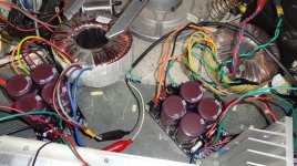
Terry, thank you for confirmation. I'm running the MOSFET OPS with my Low TIM hybrid front-end during some time and going to leave it this way - I like this setup a lot.
Preparing for putting the whole thing into a nice Italian compartment 😉
Cheers,
Valery
Preparing for putting the whole thing into a nice Italian compartment 😉
Cheers,
Valery
> I thought that they didn'tI don't really understand why something that is less linear would sound better unless the FETs have a better crossover region, but from I've read, I thought that they didn't. Oh well.
[...]
Where have you read this? Perhaps in D. Self's book ?
Cheers, E.
> I thought that they didn't
Where have you read this? Perhaps in D. Self's book ?
Cheers, E.
😀
> I thought that they didn't
Where have you read this? Perhaps in D. Self's book ?
Cheers, E.
Mr. Self hate mosfet.
Mr. Cordell love it 😀
I have VSSA variant, using lateral mosfet. It is sound good.
Now, I want to try BIGBT.
- Home
- Amplifiers
- Solid State
- Slewmaster - CFA vs. VFA "Rumble"