Ah what rail voltage are you using? I was designing for 35V rails but if we're targeting ~70V then I'll increase the bootstrap resistors. 5mA VAS current should be ample to drive either the EF3 BJT or EF2 HEXFET SlewMonster OPS, I should think?
Yes, actually I modeled with +/-70VDC 🙂
You're right - let's give the lower VAS current options.
5.6K + 5.6K gives 5.77mA
6.8K + 6.8K gives 4.74mA
Lower VAS current results in slightly higher overall distortion (up to 0.07% @ 20KHz with 4.74mA)... still not bad at all for such a simplistic topology 😉
This is my version. It have good THD profile 😎
The full schematic looks funny - a tiny IPS with a massive power section 🙂
Yes, pretty good distortion-wise.
Back to the roots 😉
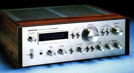
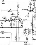
Just remembered I saw this classic approach in some rather expensive (at that time) heavy amplifier... Looked into my archives and - Bingo!
Pioneer SA-8800. Second half of the previous century 😛 1980...
Looks familiar, huh? Has got some VAS degeneration, by the way...
Just remembered I saw this classic approach in some rather expensive (at that time) heavy amplifier... Looked into my archives and - Bingo!
Pioneer SA-8800. Second half of the previous century 😛 1980...
Looks familiar, huh? Has got some VAS degeneration, by the way...
Attachments
I remember that amp. Did its predecessor (ie: SA-9500) have the same IPS? I believe they had BJT drivers but that's about all I can recall. These go pretty cheap on Ebay, anyone know if they can economically be reworked with a CFA circuit?
The degeneration is most useful when the load is very high impedance or your OPS has very high input impedance. In this circuit it could have been there just to limit the VAS current on negative overload.
I remember that amp. Did its predecessor (ie: SA-9500) have the same IPS? I believe they had BJT drivers but that's about all I can recall. These go pretty cheap on Ebay, anyone know if they can economically be reworked with a CFA circuit?
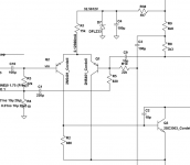
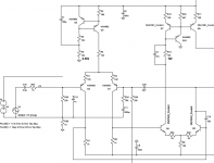
There were two generations of SA-9500 - initial one and Mk II.
Initial one had VAS loaded with CCS (1-st picture).
Mk II had balanced VAS with current mirror (2-nd picture).
Both SA-9500s had more power and less distortion (less than 0.005% total THD against 0.05% for SA-8800, according to specifications).
But for "Heartbreak Hotel" we need the simplest topology with no distortion reduction mechanisms. Clean experiment 😉
Attachments
But for "Heartbreak Hotel" we need the simplest topology with no distortion reduction mechanisms. Clean experiment 😉
That's the key - no tricks or gimmiks at Heartbreak Hotel. I'll update tonight and post the files if I get the chance.
There were two generations of SA-9500 - initial one and Mk II.
Initial one had VAS loaded with CCS (1-st picture).
Mk II had balanced VAS with current mirror (2-nd picture).
Both SA-9500s had more power and less distortion (less than 0.005% total THD against 0.05% for SA-8800, according to specifications).
But for "Heartbreak Hotel" we need the simplest topology with no distortion reduction mechanisms. Clean experiment 😉
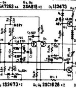
I'm interested with push pull VAS. It is easy to get high slew rate and low THD (using Hawksford cascode, etc).
How about this simple one?
Attachments
I'm interested with push pull VAS. It is easy to get high slew rate and low THD (using Hawksford cascode, etc).
How about this simple one?
Cool one. But we need "more distortion" at the moment 😀
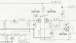
Sorry vzaichenko
in the post 3972: the circuit corresponds to the receiver Pioneer SX-737.
GEirin
in the post 3972: the circuit corresponds to the receiver Pioneer SX-737.
GEirin
Sorry vzaichenko
in the post 3972: the circuit corresponds to the receiver Pioneer SX-737.
GEirin
OK, I understand where confusion comes from.
There was another SA-8800, manufactured earlier (1975) for internal market only. The power section there is unified with SX-737.
Here is some info on this "other" SA-8800:
SA-8800 for Japan
"International" version of it is called SA-8500 (1976). Same schematic.
The picture in my earlier post is actually for the latter international version of SA-8800...
Cheers,
Valery
Last edited:
How critical is returning the FB DC blocking capacitor to the lifted ground? I ask since I noticed my rework of Wolverine has the cap connected to G2 (IPS star) and not the lifted ground. If it is a really minor thing I will leave it. If it a serious issue I will look at reworking it.
How critical is returning the FB DC blocking capacitor to the lifted ground? I ask since I noticed my rework of Wolverine has the cap connected to G2 (IPS star) and not the lifted ground. If it is a really minor thing I will leave it. If it a serious issue I will look at reworking it.
Well, LTP at the input works in a way that any differential mode signal is amplified, any common mode signal is suppressed. Having both input and NFB signals referenced to one point (lifted ground), you ensure clean differential mode functioning, suppressing any common mode noise or ripple. Otherwise, having them referenced to the different points (e.g. lifted ground and G2), any unwanted noise or ripple, possibly occurring between those two points, will be amplified.
I have a question about the OPS with MOSFETs. Was the purpose for trying the MOSFETs just to see if it would work or were you expecting some sort of benefit from using them? If so, what?
Just trying to learn something here.
Thanks, Terry
Just trying to learn something here.
Thanks, Terry
Terry I could be wrong but I think one aspect was a possible increase in output power though I don't think that was the original goal.
MOSFETs are fast devices and they are also pretty robust. They are also pretty inexpensive and readily available in most markets. It was a proof of concept and gives builders another option. For me it was an experiment to see what was possible. It just so happens it works pretty good too. It just happened that Valery had the same idea and built one before me.
I did a bode plot (measured frequency response) with the SlewBaby MOSFET OPS and the Symasui IPS and it was flat out to almost 1MHz! IIRC I set it to output 10Vp-p and run the sweep out to 5MHz taking my measurement prior to the coil. I was impressed.
The only caveat is the loss of voltage swing because of the required bias voltages involved. A MOSFET SlewMaster would benefit from IPS / driver rails ~12-15V higher than the maim high current OPS rails for maximum output. I could only get to within 9V of the rails.
So maybe the cap multiplier portion of the OPS is working against them?
If you were building a high power amp, would you use the SlewMOS or the Slewmaster?
If you were building a high power amp, would you use the SlewMOS or the Slewmaster?
The capacitance multiplier 'eats' a little swing, and so do some of the techniques like using cascodes in the IPSs. It is the price you pay for quiet, low distortion power amplifiers I suppose. The MOSFET option eats into the available swing because the gates need to be driven to a higher voltage than the base of a BJT does. This is why 'boosted rails' would be suitable for the MOSFET variant.
If I were being frugal with my PSU then the added efficiency of the BJT outputs will net you a little extra wattage, but then MOSFETs are pretty tough and stand a better chance to survive abuse BJTs might not. Tough call really. I haven't had the time to put another channel of MOSFET output to give it a proper listen, but it on the to-do list for sure.
If I were being frugal with my PSU then the added efficiency of the BJT outputs will net you a little extra wattage, but then MOSFETs are pretty tough and stand a better chance to survive abuse BJTs might not. Tough call really. I haven't had the time to put another channel of MOSFET output to give it a proper listen, but it on the to-do list for sure.
Interesting. To be honest I doubt you could ever notice a 5V difference in output. I put 36V rail amps up against 77v rail amps all the time on my A/B setup and until they are driven really hard they are step for step.
- Home
- Amplifiers
- Solid State
- Slewmaster - CFA vs. VFA "Rumble"