OK, But AR is not cheap chinese tooobs ..... 🙂
OK, it was an expression to impress. 😀
AR possibly made in China nowadays, who knows. 😀
Last edited:
 Publicly commenting on moderation is a very serious violation of forum rules. Moderation strongly recommends that all members who did so familiarize themselves with forum rules. Any questions about moderation matters are to be directed to moderation in PMs and emails ONLY.
Oh, can-you show-us this wonder with a schematic ?As you see, CFAs may have a minimum of two HF poles in the feedback loop, while with VFAs you can get along with only one.
Please take some minutes to read the link i cited, and specially the part entitled "One remark".
With everything equal elsewhere (slewmaster ?), the LTP parasitic capacitance (non linear) of the base of the transistor witch receive the feedback, combined with the high impedance of the feedback bridge (witch is usually equal to the one needed for the signal input, for DC stability reasons), create a low pass filter to the feedback signal.
While, in a CFA, we can set the feedback impedance as low as we want to reduce the phase shift, so, the influence of the emitter parasitic capacitance can be negligible.
I know this is hard for you to admit or even understood in your strange war against CFAs.
Last edited:
Well tubes have this advantage, despite their nice pair distortions, to not saturate with brutality and to be "fast" ?I heard Halcro, Soulution, Mark Levinson ... and to be honest simple and cheap chines tube crap amp have more life and music realism then those monsters.
Why???
But i believe you expected the word "simplicity" as my answer, and i agree.
I strongly recommend to Waly to analyze why IC have better performances in inverting mode ;-)
And to *build* one time in his life a CFA and a VFA with the same overall gain, open loop gain, everything equal apart the input stage, and to... listen.
With objectivity, if it is possible.
It will probably end this unproductive controversy.
And to *build* one time in his life a CFA and a VFA with the same overall gain, open loop gain, everything equal apart the input stage, and to... listen.
With objectivity, if it is possible.
It will probably end this unproductive controversy.
Last edited:
Oh, can-you show-us this wonder with a schematic ?
Sorry, it's well past midnight here, plus that I've learned it is useless to argue on this topic. You are using a lax semantic to address technical points (like the confusion between "pole in the feedback loop" and "pole in the loop gain") and aligning the terminology and fundamentals is to much free work, even for a student.
Those who want and can understand my points, will know the truth, anyway. Those who can't, or don't want to, won't lose any sleep over my posts, anyway.
Trying to move forward... Ideas for PSU features
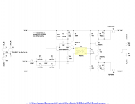
OS had previously mentioned wanting to incorporate rail shutdown facilities into a 'SlewMaster' PSU. This has been something of interest to me as well. Attached is a proposed DC detect / rail shutdown design.
Alternative ideas or constructive comments welcome. The parts used in simulation aren't necessarily what is being suggested, just the general concept.
Attachments
OS had previously mentioned wanting to incorporate rail shutdown facilities into a 'SlewMaster' PSU. This has been something of interest to me as well. Attached is a proposed DC detect / rail shutdown design.
Alternative ideas or constructive comments welcome. The parts used in simulation aren't necessarily what is being suggested, just the general concept.
Jason, looks good. I would also add a current overload shutdown feature, sensing the current either via the OPS emitter resistors or at the rails directly (will require a small value resistor in series though)...
Assuming rather high triggering current, may be implemented pretty easily with an opto-pair device as well.
What do you think?
And this is exactly what my PS regulator contains plus capacitor multiplying effect, and this was proven and it's working in real life.
Damir
And this is exactly what my PS regulator contains plus capacitor multiplying effect, and this was proven and it's working in real life.
Damir
Yes, Damir, that one is an excellent one - I thought about it right away.
Well, this one is rather simple and I like opto-coupling here.
Why not? 😉
Yes, Damir, that one is an excellent one - I thought about it right away.
Well, this one is rather simple and I like opto-coupling here.
Why not? 😉
I don't see the need for opto-coupler here, it could be done with small bjts as it use the same power supply.
Jason, looks good. I would also add a current overload shutdown feature, sensing the current either via the OPS emitter resistors or at the rails directly (will require a small value resistor in series though)...
Assuming rather high triggering current, may be implemented pretty easily with an opto-pair device as well.
What do you think?
I'm not sure about the over-current shutdown myself. Isn't that why we install fuses? I'd assume if a massive current were flowing there would also likely be a DC fault; unless, like you suggest, the limit is very high so if the amplifier were driving a near short circuit (and assuming the amplifier itself would survive such a load) it would become active.
That said, the amplifier might be the place to install a limiter as is usually suggested. With robust multiple pairs of outputs a single slope limiter can be set quite close to the SOA so as to not be active on any valid signal / load combination.
Now, other reasons to kill the rails might include HF detection so if a significant oscillation were to occur the amplifier is shut down or over-temperature detection... Thoughts?
And this is exactly what my PS regulator contains plus capacitor multiplying effect, and this was proven and it's working in real life.
Damir
The SlewMaster OPS has capacitance multipliers to feed the IPS. I'm not sure if feeding the power section via a CM is really needed. I wanted to ultimately select smaller devices and just use them as switches. A CM would require a device with a more capability in its linear (ohmic) region.
Thank you jason... what's the mosfet we can use?
Any relatively low Rds ON device that is rated to withstand at least a full rail, ideally the sum of the rails and the required current. There aren't too many higher voltage devices, say 200V or greater, with 100mΩ or less Rds ON. The specific device itself isn't critical since we would be using it as a switch.
Short circuit protection is valuable, at some time you'll get someone that shorts together the speaker wires. Fuses are slow.
I don't see the need for opto-coupler here, it could be done with small bjts as it use the same power supply.
The latch can, and perhaps should, be run from a lower voltage rail. That way the optocoupler LED can be run harder without undue dissipation in the latch. I just showed it in its simplest form running off the positive main rail.
Why the objection to a simple optocoupler? We aren't talking the photovoltaic type, just the plain vanilla transistor output. They are cheap, readily available, and known to be quite reliable. It allows me to leave my current source to float (no, it doesn't have to) and still short out its bias source with a circuit referenced to ground.
Short circuit protection is valuable, at some time you'll get someone that shorts together the speaker wires. Fuses are slow.
Yes, fuses are slow. Of course the components that are usually used in a linear supply are capable of withstanding short term gross overload, and so a fuse will provide protection.
The need for rapid action relates to saving output devices from a dangerous loading. Do we need / want to detect that at the PSU? To really protect the OPS we need more information about what it is subject to than just 'current X has been exceeded, shut it down'. A proper SOA limiter seems the better choice for adverse loading of the output to me.
I think power supply with shutdown triggered by SOA protection, DC offset protection, temperature protection, etc can be made optional. If someone want it, he can add the components. We must define the interface of this OPS to the power supply.
Then everything are modular 😀
Then everything are modular 😀
Video - TinyPic - Free Image Hosting, Photo Sharing & Video Hosting
Hello
greetings short circuit protection is important sometimes by mistake speaker wires get shorted tried a short circuit protection on a 100 watt amp it works have to experiment
with a universal HIGH POWER version can post schematic if anyone is interested
warm regards
Andrew
Hello
greetings short circuit protection is important sometimes by mistake speaker wires get shorted tried a short circuit protection on a 100 watt amp it works have to experiment
with a universal HIGH POWER version can post schematic if anyone is interested
warm regards
Andrew
- Home
- Amplifiers
- Solid State
- Slewmaster - CFA vs. VFA "Rumble"