Low TIM, low distortion hybrid front-end
Guys, I copy it here, as it is very much in line with Ostripper's "rumble" and will work perfectly with his nice Slew Monster power sections:
Low TIM, low distortion hybrid front-end
Interested? Shall I develop a PCB? 😉
Cheers,
Valery
P.S. Requires additional 6.3V AC for heating the valve...
Guys, I copy it here, as it is very much in line with Ostripper's "rumble" and will work perfectly with his nice Slew Monster power sections:
Low TIM, low distortion hybrid front-end
Interested? Shall I develop a PCB? 😉
Cheers,
Valery
P.S. Requires additional 6.3V AC for heating the valve...
Attachments
Hi thimios,
That looks like what I have. If that's fine I will quit worrying.
Hi Valery,
That looks very interesting. Please do develop a PCB.
Thanks, Terry
That looks like what I have. If that's fine I will quit worrying.
Hi Valery,
That looks very interesting. Please do develop a PCB.
Thanks, Terry
Played some music through it and as expected, it sounds just like the others.
Blessings, Terry
Terry, there must be something terribly wrong with your system setup or your hearing. Different topology, different parts, different wiring should produce noticable differences.
One passive interconnect cable interchange can be heard in a transparent system, by all means change of an active amplifier even more.
I have a question about the Wolverine VAS adjustment. Where do I measure to set it and what voltage?
Thanks, Terry
Thanks, Terry
Terry, there must be something terribly wrong with your system setup or your hearing. Different topology, different parts, different wiring should produce noticable differences.
One passive interconnect cable interchange can be heard in a transparent system, by all means change of an active amplifier even more.
What is your setup for doing A/B testing? Mine is very simple. Both amps are fed the same signal with DATC step attenuators to equalize output volume. Then both outputs are fed to a speaker switch for instant switching between amps. I feed that to JBL 4412 or 4425 speakers. With output levels equalized, these amps are virtually indistinguishable from one another.
So what setup are you using?
Edit to above. To be fair, I didn't A/B the wolverine with the other amp. I will do that tomorrow to make sure.
..
Last edited:
2 5th element
What transistors You use for VAS and predriver? MJE340/350?
VAS is 3503/1381. Pre drivers are 340/350.
I figured as the Pre drivers are much easier to get I'd use 340/350 wherever OS' original schematics said they would be suitable. If they aren't I'll swap to 3503/1381s.
One passive interconnect cable interchange can be heard in a transparent system, by all means change of an active amplifier even more.
Let's not start with that kind of stuff in this thread please otherwise the mods are going to have a lot of clearing out to do.
MJE340 are slow and with big (about 30pF) nonlinear , voltage dependant Ccb capacity, they are not suitable as VAS nor predriver for best performance. The only advantage is availability, but they are not suitable for low distortion at high frequency. Using them as predriver , they are loading VAS with this capacity, result is rapid rising THD with frequency. Use 3503/1381 and compare results.. I have never used MJE340/350, but if I swap them for 3503/1381 in simulation at predriver position (Cordell models..), it worsens THD at 10kHz about one order of magnitude compared to 3503/1381, and dominat is third harmonics (10dB over second harmonics at 10kHz ), exactly as your measurements showed.
Last edited:
I am doing some measurements now with the swapped out devices and it looks promising. Simulation appeared to mirror what you posted too. I think I'll have to replace the 340/350s in the wolverine too as that could explain the higher than expected levels of D3 there, although it's not as bad as it is with the CFA. 😀
Would those NPN/PNP transistors I posted before be suitable for the input pair? Having them in the same package would seem to be of benefit.
BC846BPN - NXP - TRANSISTOR, NPN, 65V, 100MA, SOT363 | Farnell UK
Would those NPN/PNP transistors I posted before be suitable for the input pair? Having them in the same package would seem to be of benefit.
BC846BPN - NXP - TRANSISTOR, NPN, 65V, 100MA, SOT363 | Farnell UK
BV,
Thank you for this last explanation of why the 3rd harmonic is rising in 5th Elements implementation, it makes sense and explains the ratio of 2nd to 3rd distortion products. Now if someone would post a bom with all of these considerations for the CFA-XH it would be greatly appreciated rather than a random combination of acceptable parts, I know that many of these combinations will sound very good but why not make it great and have a preferred combination that takes all of these things into consideration. As long as all the parts are current and will be in production for some time we can do this. I would add that it would be nice if the output section was also looked at the same way with a complete solution from input to output section considering final end result.
Steven
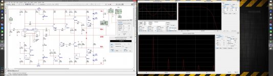
Okay, hot off the press and first I must apologise. The voltage level for my previous measurements was incorrect. I had made an error in calculation. Instead of all the ones being 14vrms, they were in fact done at 7vrms. I had divided the peak to peak voltage by 1.41 instead of the peak voltage by mistake 🙄
Either way it's all academic now because the results were for an amplifier that no one is going to build because it's flawed!
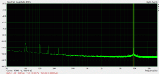
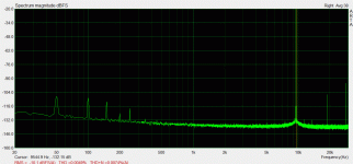
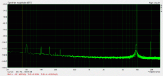
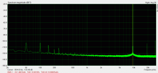
Here we go. Three graphs. All optimally biased. The first is 2.83vrms into my 9.4 ohm load, the second is 7vrms and the third is 13.5vrms which is taken ~0.5dB below clipping.


Now that's pretty impressive 😀
Next up class A.
Either way it's all academic now because the results were for an amplifier that no one is going to build because it's flawed!
Here we go. Three graphs. All optimally biased. The first is 2.83vrms into my 9.4 ohm load, the second is 7vrms and the third is 13.5vrms which is taken ~0.5dB below clipping.
Now that's pretty impressive 😀
Next up class A.
Attachments

Hi BV,
Will it be better to use MJE340/350 same hfe ranking,
or to use 3503/1831 with mismatched hfe ranking, for the pre-drivers,
I bought my 3503/1831 from Mouser and they don't stock same hfe ranking.
I'm using the 3503 from my VAS and the 1831 for the VAS CCS and I'm currently using the MJE340/350 as predrivers.
But I have extra 3503/1831, if you advice me to use them as pre-drivers, even if they mismatched ranking?
Thanks
Last edited:
It looks promising.. But it will be needed to decrease Uce (e.g like with resistor R22,R23 in CFA mod.2) to keep Pc low (max 20-30mW for one system). Thermal tracking on one chip is benefit.Would those NPN/PNP transistors I posted before be suitable for the input pair? Having them in the same package would seem to be of benefit.
2 Vostro
Better to use 3503/1831.. Do not use MJE340/350 anywhere in signal path, if you are striving for best results at high frequency. Use them is somewhere in PSU, like capacity multiplier or so.
Last edited:
"Okay, hot off the press and first I must apologise. The voltage level for my previous measurements was incorrect. I had made an error in calculation. Instead of all the ones being 14vrms, they were in fact done at 7vrms. I had divided the peak to peak voltage by 1.41 instead of the peak voltage by mistake"
Hi Matt can you tell me what attenuator used?
Hi Matt can you tell me what attenuator used?
It looks promising.. But it will be needed to decrease Uce (e.g like with resistor R22,R23 in CFA mod.2) to keep Pc low (max 20-30mW for one system). Thermal tracking on one chip is benefit.
2 Vostro
Better to use 3503/1831.. Do not use MJE340/350 anywhere in signal path, if you are striving for best results at high frequency. Use them is somewhere in PSU, like capacity multiplier or so.
I think it'd be nice if OS were to edit his original circuit diagrams then and say specifically not to use 340/350 for the pre drivers unless you really cannot get 3503/1831 because it is a little misleading.
I already have something in for R22 and R23, although to your advice they have been reduced down to 1.5k in my 25 volt operated amplifier.
Hi Matt can you tell me what attenuator used?
For these measurements it's incredibly simple. The sound card has an input impedance of 10k, so I'm using that as part of the attenuator. All I've done is put enough series resistance on the output of the amplifier to protect the sound card/reduce the signal level appropriately.
Last edited:
Guys, I copy it here, as it is very much in line with Ostripper's "rumble" and will work perfectly with his nice Slew Monster power sections:
Low TIM, low distortion hybrid front-end
Interested? Shall I develop a PCB? 😉
Cheers,
Valery
P.S. Requires additional 6.3V AC for heating the valve...
Valery,
You have piqued my interest. Please show us more starting with a large detailed schematic as a pdf file please.
Another question. If as 5th Element is has solved some of his harmonic distortion and has now created a circuit with particular components in specific places, if with adjustments for voltage difference, such as running 70v instead of 25v rails as he is, will this change how any of the components will work as long as they are all capable of handling the max voltages? Would all the transistors remain the same?
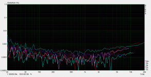
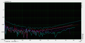
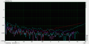
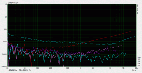
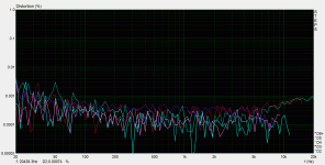
Hmm it seems like this amplifier is exceptionally sensitive to getting the bias level right and isn't so happy about being biased into class A.
It has to be said this is the first amplifier I've used where I can actually see the effect of gm doubling at play, at least I am assuming that it's GM doubling.
If the bias is set too low distortion shoots up to like 0.01%, if it's set just right it can fall down to ~0.0015% levels, take the bias up further and distortion rises up to about 0.005%, then once you enter class A it falls again down to around ~0.0015%. (This is at 9.5kHz. and for 7vrms into 9.4 ohm)
When biased into class A high order distortion just vanishes, which is really the point of class A imo, but third order goes up.
For example.

2.83vrms looks dandy either way.

Full power isn't really so pretty, 2nd and 3rd HD shoot up, but the higher orders go down.

Now here are some FFTs of how the amp reacts to biasing.
First up under biased.

Do not do this. 😱
Overbiased (note this is at its worst)

Again, try not to do this.
Optimally biased.

Much better.
And in class A.

I am not entirely sure if these results are specifically because of bad biasing or more because of how sensitive the design appears to be to having the pots on the input stage set correctly. This isn't just a case of making sure that the DC offset is zero, I mean of course, you do that, but you can get significantly different results by turning them both up and down together and finding a new zero DC offset operating point as it were.
This could be because my input pair are not perfectly beta matched, I don't know.
If done right you can effectively get rid of 2nd order products completely, introduce more if you wish and change the relative level of the 3rd order.
One thing is for sure having the thing optimally biased is clearly the way to go for high power levels, which is what everyone here would be doing anyway. Biasing anything significant into class A at 80 volt rails will fry an egg.
What surprised me here was that the bias level, when set optimally, was very narrow, one step up and things get worse, one step down and things get much worse.
In my case the best results were had with around 20mV across one 0R47 RE resistor. This is slightly lower than one would expect and might very well play out differently for different peoples amplifiers.
It has to be said this is the first amplifier I've used where I can actually see the effect of gm doubling at play, at least I am assuming that it's GM doubling.
If the bias is set too low distortion shoots up to like 0.01%, if it's set just right it can fall down to ~0.0015% levels, take the bias up further and distortion rises up to about 0.005%, then once you enter class A it falls again down to around ~0.0015%. (This is at 9.5kHz. and for 7vrms into 9.4 ohm)
When biased into class A high order distortion just vanishes, which is really the point of class A imo, but third order goes up.
For example.
2.83vrms looks dandy either way.
Full power isn't really so pretty, 2nd and 3rd HD shoot up, but the higher orders go down.
Now here are some FFTs of how the amp reacts to biasing.
First up under biased.
Do not do this. 😱
Overbiased (note this is at its worst)
Again, try not to do this.
Optimally biased.
Much better.
And in class A.
I am not entirely sure if these results are specifically because of bad biasing or more because of how sensitive the design appears to be to having the pots on the input stage set correctly. This isn't just a case of making sure that the DC offset is zero, I mean of course, you do that, but you can get significantly different results by turning them both up and down together and finding a new zero DC offset operating point as it were.
This could be because my input pair are not perfectly beta matched, I don't know.
If done right you can effectively get rid of 2nd order products completely, introduce more if you wish and change the relative level of the 3rd order.
One thing is for sure having the thing optimally biased is clearly the way to go for high power levels, which is what everyone here would be doing anyway. Biasing anything significant into class A at 80 volt rails will fry an egg.
What surprised me here was that the bias level, when set optimally, was very narrow, one step up and things get worse, one step down and things get much worse.
In my case the best results were had with around 20mV across one 0R47 RE resistor. This is slightly lower than one would expect and might very well play out differently for different peoples amplifiers.
Attachments
- Home
- Amplifiers
- Solid State
- Slewmaster - CFA vs. VFA "Rumble"