Hi Ricky,
Not sure what you mean by "Have little doubt". Anyhow, the compatibility issues I was talking about are real and well known and discussed at length at the Lynx forum.
Cheers, E.
Hi Edmond, yes compatibility issues are real for certain PCI devices/busses, electrical/routing/software/IRQ. Though i'm very interested in PC configuration but realizes it don't belong here. The thing "Have little doubt" is actual electric routing inside certain platform controller hubs and their link to CPU without going to read 700+ pages of chipset documentation.
Last edited:
Hi Matt if it's possible i want an fft analyze of your amplifier Arta based not steps.Loop back.

It's clearly not the sound card.
I want to see how 50hz shown in your case
This is absolute truth.thimios,
Now if is becoming much harder to see a real distinction between the two amplifiers, they are both looking good. I was wondering why the CFA was having such a large drop-off at high frequencies and now I see that has disappeared with your new measurements and a lower value capacitor on the input. I have been under the impression throughout the CFA vs VFA thread that the CFA would have the higher closed loop gain and bandwidth. I wonder how much lower the thd+n figures would be with a higher quality sound card for both amplifiers, it appears we are hitting the limits of your card Thimios.
All these amplifiers are high quality ,my sound card can't show accurate results.
BTW using this card i will be sure if there is big issue somewhere ...
Another thing i learned from all this effort is that ftp cable is a very good solution using this as interconnect cable.
Last edited:
Another distortion measurement with everything removed from the system that doesn't need to be connected. These are at 14vrms 9.4 ohm load class A bias.

And a 1.1kHz FFT of the same thing.

Normally I have lots of stuff connected up to where the signal source comes from, other amplifiers etc and lots of phono leads as this is a multi way active system + surround set up. This doesn't create any ground loops as per say, but it does introduce interference/noise centred around the classic 50/100/200/400Hz spectra. It doesn't muck up the measured performance at higher frequencies, but it does crap up the low stuff which is why I normally cut things off @ 100Hz.
I also have a self designed mic preamp that uses two PGA2500 chips, OLED display, micro controller etc. It has built into it relays for signal switching and circuitry included for connecting up an amplifier for making single ended measurements of amplifiers and differential measurements of bridged and class D amplifiers. It also incorporates a simple jig for making impedance measurements with LIMP and has zeners present to protect the sound card input.
For the above measurements I disconnected everything from the DSP/DAC signal source unit, unpowered every, non essential, piece of equipment connected to the system and bypassed the mic pre.
As can be seen it doesn't really do much to alter the high frequency distortion, but it does clean up the lower end significantly. As can be seen the FFT is pretty nice looking, especially as there is a decent amount of ripple on the power lines and the CFA amp isn't using the cap multiplier or any kind of front end regulation. I am using a 2nd RC filter to the input stage, a 4R7 + 1000u though. There is the provision for adding regulation to the input stage but I haven't implemented it yet.
That's what I thought, all the caps are either NPO or COG apart from the ceramics across the emitter resistors.
And a 1.1kHz FFT of the same thing.
Normally I have lots of stuff connected up to where the signal source comes from, other amplifiers etc and lots of phono leads as this is a multi way active system + surround set up. This doesn't create any ground loops as per say, but it does introduce interference/noise centred around the classic 50/100/200/400Hz spectra. It doesn't muck up the measured performance at higher frequencies, but it does crap up the low stuff which is why I normally cut things off @ 100Hz.
I also have a self designed mic preamp that uses two PGA2500 chips, OLED display, micro controller etc. It has built into it relays for signal switching and circuitry included for connecting up an amplifier for making single ended measurements of amplifiers and differential measurements of bridged and class D amplifiers. It also incorporates a simple jig for making impedance measurements with LIMP and has zeners present to protect the sound card input.
For the above measurements I disconnected everything from the DSP/DAC signal source unit, unpowered every, non essential, piece of equipment connected to the system and bypassed the mic pre.
As can be seen it doesn't really do much to alter the high frequency distortion, but it does clean up the lower end significantly. As can be seen the FFT is pretty nice looking, especially as there is a decent amount of ripple on the power lines and the CFA amp isn't using the cap multiplier or any kind of front end regulation. I am using a 2nd RC filter to the input stage, a 4R7 + 1000u though. There is the provision for adding regulation to the input stage but I haven't implemented it yet.
Each cap exposed to AC voltage swing must be NPO type. So VAS compensation, input filter, local compensation in output stage...
That's what I thought, all the caps are either NPO or COG apart from the ceramics across the emitter resistors.
Attachments

The first thing I'd suggest is if you can repeat your measurements using an FFT length of 131072 to bring mine and your measurements more in line with one another. It should improve low frequency accuracy and reduce the noise a little.
Ok that is a job for tomorrow.The first thing I'd suggest is if you can repeat your measurements using an FFT length of 131072 to bring mine and your measurements more in line with one another. It should improve low frequency accuracy and reduce the noise a little.
Well I'll make a comparison ignoring that then if you want.
Really though there's not a lot to say apart from you have higher overall noise levels and higher amounts of mains noise/buzz/interference getting through. The noise levels could simply be attributed to the FFT length and the mains stuff really isn't a concern imo, unless you've got trouble there.
What I mean by this is that when I've got all my amps and stuff plugged into my main unit I get worse grunge like that than you do, but it doesn't really affect the higher frequency performance. I mean yeah, it screws up the low stuff, you'd expect it to, but this is all 'coupled' noise, as in something being close to something else, rather than large currents flowing where they shouldn't.
If you've got a similar thing happening with your set up then it is quite possible that the mains stuff is perfectly innocuous. If it isn't what it means is that a return current, or maybe part of it, from the load on your amplifier, could be returning down the shield on a signal lead etc. This will induce all sorts of distortion nasties, but it will go away completely if you disconnect the load.
With respect to your previous measurements, longer FFT lengths will always tend to give you better results, they just take longer to gather the data. The same is true for STEPS, in the setup for that you've got the various lengths, integration time, transient time, burst pause etc. If you increase the lengths on these it can give you better results and it is sometimes necessary to increase them for some hardware, but it takes longer as a result.
I have a feeling that this is more about component value optimisation rather than implementation or component choice error.
With some tweaking I've managed to get the 1 watt class A distortion to look like this.
I still need to alter the value of R15 and R20 a little, according to simulation, but things are moving a bit in the right direction.

This is certainly much nicer than before and I could probably get it a little lower just be reducing the attenuation of the resistor divider and increasing the SnR.
With some tweaking I've managed to get the 1 watt class A distortion to look like this.
I still need to alter the value of R15 and R20 a little, according to simulation, but things are moving a bit in the right direction.
This is certainly much nicer than before and I could probably get it a little lower just be reducing the attenuation of the resistor divider and increasing the SnR.
Attachments
Can anyone explain why the third harmonic is rising like it is on the top end and I would have thought that the 3rd would have been below the 2nd in total level?
This is a symmetrical amplifier design on the input stage, if you get the pot values just right you can get the 2nd harmonic to cancel out pretty well, such that third dominates.
I am thinking of using these for the input pair in the next PCB version.
BC846BPN - NXP - TRANSISTOR, NPN, 65V, 100MA, SOT363 | Farnell UK
Any objections?
I honestly do not know why the third order on my design shoots way up with drive level. I mean the second harmonics do too, to an extent, but nothing like what the third does. 2nd largely remains below 0.001% if the pots are adjusted correctly.
Simulation predicts a small increase in third as you approach the supply rails, but not like what I am seeing. I am wondering if this has anything to do with the fact that my input pair aren't matched in any way. I don't have any complementary pairs of small signal transistors that will beta match.
Here for example is the amplifier again driving the 9.4 ohm load at 14v in class A. Now we've got slightly lower 2nd order.

Here's possibly something interesting about the 'problem' as it were for those of you with more knowledge than I to put to your brain cells.
This is the amplifier driving the 9.4 ohm load optimally biased 3 volts peak to peak before clipping occurs.

Distortion increases, no surprises there. The level of the 2nd order doesn't bother me so much, but what the third order does isn't exactly what I would call perfect.
Here is the same thing, but this time done without any load connected.

2nd order goes down a bit, the higher order products go down a decent amount at high frequency (to be expected as crossover distortion goes away) but the third order remains as good as unchanged.
Clearly this isn't a case of induction based distortion, or anything of the like where nasties imposed on the power rails are finding their way back into the amplifier circuitry in some way, otherwise you'd expect the distortion to completely go away with the load disconnected.
What I find somewhat interesting is if the 3rd order distortion is looked at in a different way.

Here we have it plotted on a decibel scale and obviously we start to lose accuracy at the lower frequencies as we're down in the 0.0003% type area. Needless to say our eyes are pretty good at seeing where one could place a line of best fit and really from around 60Hz up until around 15kHz, we've got a straight line. If looked at closely enough the third order is basically rising at 6dB per octave. This cannot simply be coincidence. What it means I'm not yet sure, but it might be a clue to what's causing the distortion in the first place.
One things for sure though, if you want to optimise the performance of this amplifier you need to measure the distortion and fiddle with the input stage pots. starting off with them both at pretty much a maximum and then decreasing them slowly. Turning one down a little, letting the DC offset increase to say 200mV, then decreasing the other one down till the DC = zero again. All the while watching the 2nd order on the FFT. As you keep decreasing the pots down you will get to a point where the 2nd order reaches a minimum and turning them down any more will cause it to start increasing again. Where you stop is the minimum position and you end up with a plot like at the top of this post. This behaviour might change mind you if you've got perfectly matched input transistors.
Here's possibly something interesting about the 'problem' as it were for those of you with more knowledge than I to put to your brain cells.
This is the amplifier driving the 9.4 ohm load optimally biased 3 volts peak to peak before clipping occurs.
Distortion increases, no surprises there. The level of the 2nd order doesn't bother me so much, but what the third order does isn't exactly what I would call perfect.
Here is the same thing, but this time done without any load connected.
2nd order goes down a bit, the higher order products go down a decent amount at high frequency (to be expected as crossover distortion goes away) but the third order remains as good as unchanged.
Clearly this isn't a case of induction based distortion, or anything of the like where nasties imposed on the power rails are finding their way back into the amplifier circuitry in some way, otherwise you'd expect the distortion to completely go away with the load disconnected.
What I find somewhat interesting is if the 3rd order distortion is looked at in a different way.
Here we have it plotted on a decibel scale and obviously we start to lose accuracy at the lower frequencies as we're down in the 0.0003% type area. Needless to say our eyes are pretty good at seeing where one could place a line of best fit and really from around 60Hz up until around 15kHz, we've got a straight line. If looked at closely enough the third order is basically rising at 6dB per octave. This cannot simply be coincidence. What it means I'm not yet sure, but it might be a clue to what's causing the distortion in the first place.
One things for sure though, if you want to optimise the performance of this amplifier you need to measure the distortion and fiddle with the input stage pots. starting off with them both at pretty much a maximum and then decreasing them slowly. Turning one down a little, letting the DC offset increase to say 200mV, then decreasing the other one down till the DC = zero again. All the while watching the 2nd order on the FFT. As you keep decreasing the pots down you will get to a point where the 2nd order reaches a minimum and turning them down any more will cause it to start increasing again. Where you stop is the minimum position and you end up with a plot like at the top of this post. This behaviour might change mind you if you've got perfectly matched input transistors.
Attachments
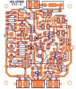
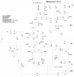
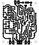
Can one of you who has built a running Wolverine IPS tell me which schematic you used? The foil pattern I used is attached. There are parts marked OPT2 that I left off. I also notice on the parts layout DC6 is circled. I used a 1n4148 there. Anyway my board is oscillating so I want to make sure something wasn't changed along the way that I missed.
Thanks, Terry
Thanks, Terry
Attachments
Hmm lemme have a look.
I also used a 1n4148 for that position.
Option 2 as far as I am aware is using a transistor to protect the VAS instead of the diode. The diode appeared to work great for me, so I thought why bother using a transistor when a simple diode will do.
The version you've built is slightly different to mine, but it's only really one of the current sources that changes a bit, so this shouldn't really affect stability.
I don't know what transistors you used, but I used MJE350s for Q10 and Q11.
I also used 992s for Q4 and Q5.
I am not exactly sure what OPT1 is though. From what I can tell with the amp in its standard form you connect the anode of D3 to the emitter of Q3, which is turned on via Q1 and conducts current into D3 to work the bias for the cascode transistors.
If you choose to go with OPT1 it looks like you remove Q3 and connect the anode of D3 to ground instead?
Either way, I didn't go with OPT1, I left Q3 in place and connected the anode of D3 to the emitter of Q3.
I don't know if that was of any help.
My current CFA board has the provision for installing some LM317/337s to regulate the input pair. This would replace the Zener regulation that OS uses. Normally you'd need to use Zener shunt regulation because a series reg like the 317/337 wouldn't work up high enough in voltage to support the 70-80 volt rails people are using here. As I am only using low voltages with mine the 317/337s fit.#
As the input pair only require a low voltage supply you could use a zener shunt reg followed by a traditional series reg, or use a small separate transformer for a regulated supply, but the VAS, especially if you use the Hawksford, H version, actually needs more voltage swing than the output stage.
As it stands I probably wont install the regulators until the next board revision because this one needs making again for some improvements.
I had toyed with the idea of installing a boosted supply from the main PSU to power the VAS, giving the amp a bit more headroom and that would in turn feed the regulated IPS, but unless I was really squeezed for power, or the performance was needed I think that might be over kill. Plus it would also give the amp the ability to send the +PD and -ve lines to a higher and lower voltage than the output stage could swing, or the main rails could reach, which could give me problems for the extra stuff I want to implement.
I found the issue. I had one jumper unsoldered at one end. Plays OK now. I ran square waves through it as just an IPS and they looked very good. Through the OPS not as good. Looks like there may be something in the OPS that is causing problems. Played some music through it and as expected, it sounds just like the others.
Blessings, Terry
Blessings, Terry
So far I like the original CFA. I can't hear any difference between them and it goes together very well. The guys who like looking at squiggly lines on a screen may have a different answer. I will build OS's latest mod tomorrow and I'll let you know what those square waves look like. I don't expect any audible difference.
Thanks, Terry
Thanks, Terry
Hey Jason,
That looks great! Looking forward to the Gerbers.
I have a couple questions about the OPS. Mine seem to have a problem with thermal runaway. Not bad but there. The drivers still run pretty hot even with a 150R in there. Is it possible that the drivers are over heating and causing the bias to rise? I have to run the bias at about 5mV per emitter to keep the heat down and then I see a ripple in the center of the sine wave that is probably crossover distortion. Almost every amp I have built has the drivers on the main heatsink. Anyway, can this be causing it? I can make larger heatsinks for the drivers but can I just keep lowering the bias on those until the issue goes away?
Thanks, Terry
The drivers still run pretty hot even with a 150R in there.
when the ambient temperature is 26C then the temperature on drivers reaches 47C
- Home
- Amplifiers
- Solid State
- Slewmaster - CFA vs. VFA "Rumble"