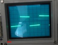
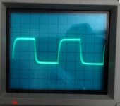
OK, I swapped out the A1220/C2690 for KSA1381/KSC3503. I pulled C2 and took some measurements. The square waves are better but not like thimios's. I am attaching some pics. I attached the probe at the output of the emitter resistors this time to get ahead of the L/R. Just to check, I also attached the scope to the PD on the IPS and the scope looks identical so this is definitely happening in the IPS.
Blessings, Terry
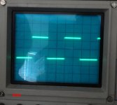
EDIT; OK, out of curiousity, I just hooked up my completed VSSA based on this very same board and the waveforms look identical to these so now I'm going to check some of my other amps to see how they look by comparison. I would suspect my scope but the tone generator direct shows perfectly square waves. I'll get back to you.
Blessings, Terry
EDIT; OK, out of curiousity, I just hooked up my completed VSSA based on this very same board and the waveforms look identical to these so now I'm going to check some of my other amps to see how they look by comparison. I would suspect my scope but the tone generator direct shows perfectly square waves. I'll get back to you.
Attachments
Last edited:
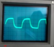
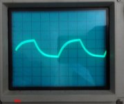
OK, fresh back from testing some of my other amps. Surprisingly, or maybe not, the purest looking 100K square wave was the Ovation NX. The 100K wave looked about like the 20K wave does above. I checked the Fetzilla, SKA GB150, DX Super A, DX MKIII, And Ovation nx. The squarest was the Super A but it has an overshoot and blew a fuse while I was testing. The MKIII was fairly square but tilted in on both sides. The FetZilla had bad squiggly lines as did the GB150. May have some oscillation I didn't know about. To be honest, I never tested any of my amps above 20K before. Didn't think it mattered. This Slewmaster concept is going to teach me a lot, I can see that now.
Blessings, Terry
Blessings, Terry
One thing I just checked was the waveform as it is being applied to the input pair bases, it has the same shape as the output. My input filter is intact. I see an amplified version of precisely what is being applied to the input pair. It looks much like Terry's shots. I'm going to see about the input filter section.
Thanks Waly.
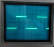
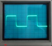
Terry, I just raised the input filter cut-off frequency (I popped in the values OS has on his CFA-XH schematic, R4=220R and C2=100pF) and get what I expected - square waves out. In a real build I'd rather have a lower cut-off frequency than to be able to say 'look at my marvelous high powered square waves'. If you want to satisfy your curiosity you can try it. My set-up wasn't fond of 100kHz squares and popped a fuse (no damage but it likely set something into instability).
Terry, I just raised the input filter cut-off frequency (I popped in the values OS has on his CFA-XH schematic, R4=220R and C2=100pF) and get what I expected - square waves out. In a real build I'd rather have a lower cut-off frequency than to be able to say 'look at my marvelous high powered square waves'. If you want to satisfy your curiosity you can try it. My set-up wasn't fond of 100kHz squares and popped a fuse (no damage but it likely set something into instability).
hehe guys dangerously playing with square balls 😀
P.S. smoked zobels, burnt fuses, smoked semis
P.S. smoked zobels, burnt fuses, smoked semis
Last edited:
hehe guys dangerously playing with square balls 😀
More like trying to put square pegs in round ears 🙄. I only did it just to prove where the 'rounding' was coming from: the 220kHz cut-off of my input filter design. No actual fault in the amplifier or device choices.
No issue with the Zobel or semis for me, I put in small fuses for the sketchy stuff 😉
Thanks Waly.
Terry, I just raised the input filter cut-off frequency (I popped in the values OS has on his CFA-XH schematic, R4=220R and C2=100pF) and get what I expected - square waves out. In a real build I'd rather have a lower cut-off frequency than to be able to say 'look at my marvelous high powered square waves'. If you want to satisfy your curiosity you can try it. My set-up wasn't fond of 100kHz squares and popped a fuse (no damage but it likely set something into instability).
Why to filter so heavily? 100 kHz squares should go through unaffected, why bother with CFA then? 😉
Why to filter so heavily? 100 kHz squares should go through unaffected, why bother with CFA then? 😉
Having the 10th harmonic of 22kHz only down by -3dB isn't good enough? I was previously setting the filter quite a bit higher (~1.6MHz IIRC) but can't say I hear any difference. OS's values set the cut-off at more like 4.8MHz, so how far into the RF range should be allowed?
You guys are the ones who suggested playing a 100k square wave. Like I said, I have never tried it before. AFAIAC, I can't even hear 20K anymore. I know none of my favorite amps liked it. Blew both fuses in my Super A. IMO the VSSA sounds very good so maybe it doesn't need adjustment in the input filter. Do we really want it trying to play radio waves? I know the sine waves look beautiful without any misshape and this amp, on +-77V rails starts clipping at 41Vac into 8R which means it's outputting 210 watts. I haven't had a chance to let it play any more because I have been chasing all this stuff. I'll try to get it set back up and let it play for a while. Meanwhile we need to quit bugging Jason so he can create some Gerbers. 😀
Oh, I'm not being bugged, I just didn't want to see you replacing everything chasing a non-problem. I just verified it for myself so I can be absolutely sure I had my facts straight when I made a statement.
I have no sound different with heavy filtering input, too. But my VFA with more slew limiting sound differently than my CFA.
I want to know how VFA sound, if it have high slew rate like CFA, but I don't have time to build IPS something like "spook-leach".
I want to know how VFA sound, if it have high slew rate like CFA, but I don't have time to build IPS something like "spook-leach".
If Jason can find time to do Gerbers for both I will order boards and build them. I should have two full sets of OPS by then and can do a proper A/B with them. I would try etching like you but the Photo sense boards cost more than factory boards so I don't see the sense in it for me, pardon the pun.
Do you think I should make changes to the input filter?
I don't personally feel it is required, but the choice is an individual one. If it sounds good to you then leave it. The whole point of an input filter is to attenuate the high frequency crap we don't want entering our amplifiers while passing what we do want. The nature of these filters has me follow the guideline that the cut-off should be out of band by a factor of 10 to achieve maximal effectiveness without having meaningful impact on the band we want to preserve.
For audio we generally accept the desired band to be 20Hz to 20kHz, so a filter on the low end should have its cut-off at 2Hz and on the high end the cut-off should be 200kHz. We don't want to get any closer to the 'pass band' lest we roll off desired frequencies, or introduce too much phase shift. However, setting the filters too far from the pass band will begin to let in too much of what the filter is there to keep out. If you want to go to the next level then I personally would go to a factor of 100 for setting the filters but no further.
OK so if I'm understanding this correctly, the input filter on mine is 10K/470pf. Lazy Cat is suggesting 560 Ohm/100 pF. Is this correct?
Terry,
210 watts with five pairs of outputs? That doesn't sound like what OS is quoting?
I'm just reporting what I see on my scope and DMM.
- Home
- Amplifiers
- Solid State
- Slewmaster - CFA vs. VFA "Rumble"