Hm, maybe a value is wrong in the bias circuit and you aren't getting into the correct range. R103 and R107 affect the temperature coefficient and bias voltage range. Did you use a 500Ω potentiometer? Might have misread the schematic and place a 200Ω one?
We don't want to allow the collector-base circuit to be open, the bias circuit basically shuts off and will allow maximal current to flow (of course you are using your bulb limiter, so the experiments shouldn't damage anything).
Based on the voltages you gave a short while ago you should be getting bias current to flow in the OPS using the prescribed values for R103-R107.
I just had another look at you pictures. Do I see 4.7kΩ for the base stoppers? R116, R119, R120, R123, R124, R127, R128, R131, R132 and R135 should be 4.7Ω
Probably a dumb question but have you checked for solder bridges on the VBE multipliers? Did you use NPN for both?
Probably a dumb question but have you checked for solder bridges on the VBE multipliers? Did you use NPN for both?
He seemed to be getting an appropriate voltage across the VBE circuit to get bias current in the outputs, but it looks like 4.7kΩ base stoppers might be to blame. I'll have to simulate the effect.
Simulation shows the high value of base stopper will kill any chance of getting the OPS to bias up. My apologies for not noticing those resistor values when you posted the pictures before. I spent more time looking at the pre-driver / driver parts to check for issues there.
I see some different values for R113, R114 & R115 between different schematics. Being I'm running 65 volt rails should I stay lower on those values?
Simulation shows the high value of base stopper will kill any chance of getting the OPS to bias up. My apologies for not noticing those resistor values when you posted the pictures before. I spent more time looking at the pre-driver / driver parts to check for issues there.
I have more fun and learn more about circuit operations when stuff like this happens. It's kind of boring if everything goes smoothly.
I have more fun and learn more about circuit operations when stuff like this happens. It's kind of boring if everything goes smoothly.
Your singing my song!!!!
Resistors R114 & R115 together with capacitors C110-C113 form an RC filter for each rail to help keep ripple off the driver collectors, pre-driver collectors and input to the capacitance multipliers. They were originally 4R7 but can be 10R with no performance issue and lower ripple to the rest of the circuit.
Resistor R113 basically determines the current flowing through the drivers, Q107 & Q108 and was originally 68R. At higher rail voltages this can allow the drivers to run pretty warm, so higher values of up to 150R have been used. I'd suggest using the lowest value that allows you to be comfortable with how warm the drivers are running. The higher current through R113 (~25mA) is desirable if the ~2W per driver dissipation is managed with adequate heat sinking.
Resistor R113 basically determines the current flowing through the drivers, Q107 & Q108 and was originally 68R. At higher rail voltages this can allow the drivers to run pretty warm, so higher values of up to 150R have been used. I'd suggest using the lowest value that allows you to be comfortable with how warm the drivers are running. The higher current through R113 (~25mA) is desirable if the ~2W per driver dissipation is managed with adequate heat sinking.
I have more fun and learn more about circuit operations when stuff like this happens. It's kind of boring if everything goes smoothly.
Glad you are gracious about it. I tend to feel somewhat responsible if things don't go well, even if those things aren't within my control. I like to see smooth builds. It makes me feel like I did my part well when things work first shot.
I've gotten into a bad habit of trusting the wholesalers too much. I check the resistance of every resister I pull out of my racks but if I read it on the bag from the wholesaler, I use it.
MOSFET Option
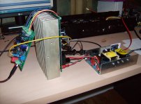
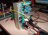
I can now confirm vzaichenko's (Valery's) findings about the ability to adapt the design to the use of MOSFETs without much ado. No physical 'hacks' required. I built my example on a 2P OPS board.
I chose to use 470Ω for R113 and to install C114. Transistors Q105 and Q106 are omitted and a jumper from B-E installed in their place. Components C107, C109 and R110 are omitted. The original 4.7Ω BJT 'Base Stoppers' R116, R119, R120, R123, R124, R127, R128, R131, R132 and R135 become MOSFET 'Gate Stoppers' of 220Ω. Driver compensation CSA and CSB are installed. Gate protection zener diodes are installed on the back of the board to protect the MOSFETs. I used IRFP240 and IRFP9140 outputs from Vishay.
R103 and R107 are 100Ω and 2.2kΩ respectively, but this is quite overcompensated. Running on +/-45V rails the OPS bias starts off at 170mA per pair and takes 30 minutes to settle to 90mA per pair on my smallish heat sink that reaches a terminal temperature of 41°C (a 16°C rise over ambient). The small driver heat sink operates at about 30°C. Clearly I need to tweak the thermal compensation temperature coefficient to better control the OPS bias, but overcompensated is at least erring on the safe side.
Attachments
Is this reversed? R103/2K2, R107/100R? I read back through the other thread and didn't see or understand why the predrivers were removed. Can you explain?R103 and R107 are 100Ω and 2.2kΩ respectively, but this is quite overcompensated.
Thanks, Terry
Is this reversed? R103/2K2, R107/100R? I read back through the other thread and didn't see or understand why the predrivers were removed. Can you explain?
Thanks, Terry
Thanks Terry, I reversed my values. Too late to edit it.
The pre-drivers are smaller TO-126 devices and aren't on any heat sink, so getting them to pass enough current to drive the MOSFET gates will make them hot. Using the drivers instead allows some heat sinking and thermal compensation for them, so they can be run hard enough to properly drive the MOSFETs. Valery tried using both and felt there was little to be gained by doing so. Without any direct measurements I can't say, but my feelings are we are likely best to just use the single EF stage to buffer the MOSFET gates. Seems to work in practise.
Thanks, just trying to learn. The only Vertical MOSFET amps I've built were Aleph-X and SKA GB150. Both very different than what we have here. I just wondered if using the pre-drivers were bad or just unnecessary. I saw that at first he didn't even use the drivers. I'm still waiting on the MOSFETS. I thought I had enough but didn't.
Blessings, Terry
Blessings, Terry
Very cool Jason!
Yes, because of significant change in bias voltage, Vbe multiplier overshoots a bit, so there is some room for improvement here (though, it is not critical, just a matter of inspiration for perfection 😉)
Terry, one pair of drivers is still needed - yes, it works without them, but distortion is higher. One pair of drivers is exactly what we need here.
- Home
- Amplifiers
- Solid State
- SlewMaster Builds