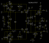
The mini was designed around the TO-3P / TO-247 package. It would likely be possible to use the TO-264 package if you don't expect the whole device to reside under the board and are willing to space the board a little further off the heatsink.
Hi jason, and what about biasing or other eventualy changes as alf16 is 2 renesas like in one package?
Marc Gautsch
Hi Marc, I don't think bias levels need to change. So long as the heat sink is adequate on the driver transistors changing one resistor (I'm away from my computer with the schematic, sorry no reference right now) will run the drivers at a higher current if someone wishes to do so.
Hi Marc, I don't think bias levels need to change. So long as the heat sink is adequate on the driver transistors changing one resistor (I'm away from my computer with the schematic, sorry no reference right now) will run the drivers at a higher current if someone wishes to do so.
Thanks for answer. I am routing a mini OPS version with To264 cap multiplier for IPS on board. Board fit in 76x100mm area. Work not ended yet.
Marc
Thanks for answer. I am routing a mini OPS version with To264 cap multiplier for IPS on board. Board fit in 76x100mm area. Work not ended yet.
Marc
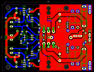
Here my attempt ..... PCBoard mesure 76x100mm in two layers
Marc
Attachments
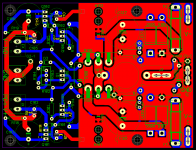
Here my attempt ..... PCBoard mesure 76x100mm in two layers
Marc
Are your boards manufactured in France..?..
Are your boards manufactured in France..?..
I achieve layout job under diptrace. With gerber files i can have for 25$ including shipping 10u from Dirt Cheap Dirty Boards
For this particular layout i don't up to time order any board. It was the same for ECC88 IPS. Layout job was done and Terry achieve groupbuy.
Marc
Nice layout ,but you must connect one rail to the fuse like in attached picture 🙂
Regards,Alex
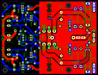
Yes alex you have right. Rail is connected through under layer tracks but lefting upper layer tracks....i will made correction.
Thanks for pointing.
Marc
Marc,
Will the heatsink for Q1, Q105 &Q106 clear R114, R115 & C101?
Sent from my HUAWEI MT7-L09 using Tapatalk
Will the heatsink for Q1, Q105 &Q106 clear R114, R115 & C101?
Sent from my HUAWEI MT7-L09 using Tapatalk
Nice layout ,but you must connect one rail to the fuse like in attached picture 🙂
Regards,Alex
Here is modificated layout
Attachments
Marc,
Will the heatsink for Q1, Q105 &Q106 clear R114, R115 & C101?
Sent from my HUAWEI MT7-L09 using Tapatalk
Heatsink will go over R114/115/106. Allowed space let install a 4mm alumium thick piece as heatsink.
Marc
Heatsink will go over R114/115/106. Allowed space let install a 4mm alumium thick piece as heatsink.
Marc
Hi Marc,
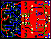
Can you move those three resistors enough to allow the heatsink to sit on the top surface? I hate burying parts below a heatsink unless absolutely necessary.
Hi Marc,
Can you move those three resistors enough to allow the heatsink to sit on the top surface? I hate burying parts below a heatsink unless absolutely necessary.
Hi Terry here is the best i can do with in to keep 100mm length board... size on picture are in mm
Marc
Attachments
Last edited:
That's perfect. It is just a piece of sheetmetal. This looks very cool. Can't wait try one.
Let me Know if you want files.... Board is disgn for To247 or To264 transistors
Marc
I don't see where you would need more than 20ma driver bias for latfets.
In fact , I would go the other way and use 220-270R for driver Re.
Then you would just need a thin <1mm sheet for a driver heatsink.
PS - both 5 pair BJT or Hexfet just use 150R/ @9ma class A on the
driver pair.
OS
In fact , I would go the other way and use 220-270R for driver Re.
Then you would just need a thin <1mm sheet for a driver heatsink.
PS - both 5 pair BJT or Hexfet just use 150R/ @9ma class A on the
driver pair.
OS
Hi Os maybe (surely) it's a mistake from me : i was thinking that the double die transistor (ALFET ALF16N16W/ALF16P16W) would need double bias level because of the //die in the same package...
Marc
Marc
Idefixes
I've asked a related question in another thread and am glad to see this addressed here. I'm sure ostripper will correct me if I'm mistaken but the transconductance (Siemans) of the part seems to determine the bias required and how much current the part can deliver to the speakers.
I've asked a related question in another thread and am glad to see this addressed here. I'm sure ostripper will correct me if I'm mistaken but the transconductance (Siemans) of the part seems to determine the bias required and how much current the part can deliver to the speakers.
Have another suggestion for you. Rotate the fuses by 90 degree (would tossed extra wholefoods plain clips could also be used) this will fix the long return path for D106 to Gnd. It also means the mounting holes will have to move.
Sent from my HUAWEI MT7-L09 using Tapatalk
Sent from my HUAWEI MT7-L09 using Tapatalk
- Home
- Amplifiers
- Solid State
- SlewMaster Builds