The ops in post 406 is good. The red and green boxes are indicating parts left out/added to the boards for the output mosfets you have. If you instead use the bjt output devices the boards were originally designed for you will populate all the parts. Since you all ready have the mosfets coming I would build with them.
I am no engineer, just a simple mechanic. There is enough info presented here for me to get good results. I did my best to read and understand what was presented...This led to me gaining some knowledge....I asked some questions...got good answers and now have some of the best sounding amps I have ever owned.
Evan
The 'marked up' schematic shows how to configure the boards for using MOSFETs as output devices. The items in the red boxes are omitted and changes (or additions) are noted in green.
My apologies for the use of abbreviations. A BJT is a Bipolar Junction Transistor, a transistor in possibly the most common sense. Around the forum you often see abbreviations and acronyms used such that it can seem like a different language sometimes. I have a formal education in electronics, so I sometimes find the electrospeak just happens.
The bulb limiter is a very useful tool, even better than safety resistors in my opinion. You will need, and I assume you have, a multimeter at absolute minimum for test gear.
JK , is the pdf " running a slewmaster ips in isolation" a part of something
more. And , is it a downloadable PDF ? Nice work - that part ...
I could add that to all my IPS booklets , unless you already made them ??
It's freakin' hot here (30C+). Summer is here. The Slew does nice in
the hot weather. Only gets 38-40C while pushing 200W !!
Thanks ,
OS
more. And , is it a downloadable PDF ? Nice work - that part ...
I could add that to all my IPS booklets , unless you already made them ??
It's freakin' hot here (30C+). Summer is here. The Slew does nice in
the hot weather. Only gets 38-40C while pushing 200W !!
Thanks ,
OS
The ops in post 406 is good. The red and green boxes are indicating parts left out/added to the boards for the output mosfets you have. If you instead use the bjt output devices the boards were originally designed for you will populate all the parts. Since you all ready have the mosfets coming I would build with them.
I am no engineer, just a simple mechanic. There is enough info presented here for me to get good results. I did my best to read and understand what was presented...This led to me gaining some knowledge....I asked some questions...got good answers and now have some of the best sounding amps I have ever owned.
Evan
man you seem to get exactly what i'm after
The 'marked up' schematic shows how to configure the boards for using MOSFETs as output devices. The items in the red boxes are omitted and changes (or additions) are noted in green.
My apologies for the use of abbreviations. A BJT is a Bipolar Junction Transistor, a transistor in possibly the most common sense. Around the forum you often see abbreviations and acronyms used such that it can seem like a different language sometimes. I have a formal education in electronics, so I sometimes find the electrospeak just happens.
The bulb limiter is a very useful tool, even better than safety resistors in my opinion. You will need, and I assume you have, a multimeter at absolute minimum for test gear.
terry's schematic causes more questions
so if the last 4 are omitted why make the board for 10
in the red box the mosfets not crossed off is other brand numbers of mosfets
what is going on here?
ok so assume the irfp are used, what is the green lines about in terms of adding something or removing something.... what?
Number of output pair is up to builder. More devices to share the load will be able to deliver more power.
The output parts not crossed off are BJT devices. Not better just different.
The output parts not crossed off are BJT devices. Not better just different.
JK , is the pdf " running a slewmaster ips in isolation" a part of something
more. And , is it a downloadable PDF ? Nice work - that part ...
I could add that to all my IPS booklets , unless you already made them ??
It's freakin' hot here (30C+). Summer is here. The Slew does nice in
the hot weather. Only gets 38-40C while pushing 200W !!
Thanks ,
OS
I have that page in PDF and it is posted somewhere in the main thread already. It is located >HERE<. I was going to work on documentation at one point, but did not pursue it. If it is useful then by all means use it. I could do a complimentary page for testing the OPS in isolation as well if you think it would be beneficial.
Summer weather would be nice. 2C and wet today. Hopefully warmer weather will come soon.
Last edited:
man you seem to get exactly what i'm after
terry's schematic causes more questions
so if the last 4 are omitted why make the board for 10
in the red box the mosfets not crossed off is other brand numbers of mosfets
what is going on here?
ok so assume the irfp are used, what is the green lines about in terms of adding something or removing something.... what?
Use the one jwilhelm posted in post 406. The one Terry posted just before that wasn't the final MOSFET arrangement. Populate a full set of outputs. The gent who marked up the schematic built a test board with fewer pairs and reflected that in the schematic. He also didn't actually change the device symbols either, just altered the text labels.
so does that mean they should be used?Number of output pair is up to builder. More devices to share the load will be able to deliver more power.
The output parts not crossed off are BJT devices. Not better just different.
if the are called for by whoever made that schematic
there must be a reason for it.
10 45 now and 4 nights and still not any closer to ordering parts.
what are the mosfet you used?
jason
i have ordered 2 626va 55-0-55, 2 10 x 6 heatsink and 2 5 x 6 heatsink. these will be high freq tig welded together to end up at 15 x 6. chassis are being worked on now . these are going to look tenor ampish. 10 irfp 240 and 10 irfp9240, soft starts each amp will have 60000uf cap and dual rectifiers.
i can build anything, fab anything, weld anything, machine anything.
i have no test gear just my ears
building tube amps are simple due to point to point wire no boards.
i have never heard the term bjt and have no clue what you are talking about.
you know a person does not need to be a electronic tech to build anything just need basic skills and a desire to . i have all that but just that.
i have used safety resistors on each leg before with great results .
terry posted the cfa schematic above , this took about 1 hour to do material list.
he also posted the ops schematic showing red boxes and green lines what is this about?
so if my boards i have are made the way they are what mosfet to use in it that way without board changes?
I wouldn't tig weld the heat sinks together. They will distort and turn to mush from the heat. Better to bolt them. The ends are usually flat half fins so the have lots of surface area to conduct through.
so does that mean they should be used?
if the are called for by whoever made that schematic
there must be a reason for it.
10 45 now and 4 nights and still not any closer to ordering parts.
what are the mosfet you used?
What speakers are you driving ?
I've not built the IRFP versions, but 3 pair FET should be a similar output
to a 5 pair BJT.
The 5 pair BJT is SCARY ! I can shake the whole house - all 1K sq. ft.
of it.
5 pair IRFP must be able to "wake the dead" !
Since the MOSFET bias is higher , I would recommend very large heatsinks
(5U - 12-15" long). I only have 3U - 14" - just right for the 5 pair BJT.
Don't be scared , any flavor of this output stage runs REAL nice.
OS
OS,
Moving back to the correct thread, considering that a mere 60 watts is enough to driver my speakers and I am that was with a single channel per side and a passive crossover do you think that a single Sanken MT-200 pair would produce more power than that H/K integrated which I would split and only use for the bass mid driver? I'll only need about a 15 watt amp for the tweeter section. So even if I double the power of the H/K for major headroom your talking about a 120 watts and 30 watts for the second amp. What output devices would you use if size is a major part of the issue?
Moving back to the correct thread, considering that a mere 60 watts is enough to driver my speakers and I am that was with a single channel per side and a passive crossover do you think that a single Sanken MT-200 pair would produce more power than that H/K integrated which I would split and only use for the bass mid driver? I'll only need about a 15 watt amp for the tweeter section. So even if I double the power of the H/K for major headroom your talking about a 120 watts and 30 watts for the second amp. What output devices would you use if size is a major part of the issue?
OS,
Moving back to the correct thread, considering that a mere 60 watts is enough to driver my speakers and I am that was with a single channel per side and a passive crossover do you think that a single Sanken MT-200 pair would produce more power than that H/K integrated which I would split and only use for the bass mid driver? I'll only need about a 15 watt amp for the tweeter section. So even if I double the power of the H/K for major headroom your talking about a 120 watts and 30 watts for the second amp. What output devices would you use if size is a major part of the issue?
The tweeter/mid only use <20% of the current in typical source material.
Some synth music/ classical is more HF based , of course.
So , 50W ( 1 pair MT-100) for the tweeter / 50W for the mid /
>100 to 200W for the bass.
the 50 watter's could be simple CFA's with simple EF2 output stages.
MDJ31/32 surface mount for drivers - all a tiny smd package running
off of 40V rails.
The "Big one" would be a true blue slew - EF3 /400VA sub/ bass amp.
That's how I would do it - along with a good IC based active X-over.
PS - you are correct , some (single pair) MT-200 amps are rated 125W/ch.
OS
I have a pair of Lazy Cat's little VSSA amps and those are so damned small, 100 watts I think. So I would expect the mini-slew with two pairs that some have made would do the trick, but is that then considered an EF2 or is it still and EF3?
I have a pair of Lazy Cat's little VSSA amps and those are so damned small, 100 watts I think. So I would expect the mini-slew with two pairs that some have made would do the trick, but is that then considered an EF2 or is it still and EF3?
"Slewbaby" (2 pair) is still a EF3 with BJT's. EF3's really do a woofer "justice".
EF3 high damping/real low Z "grabs" that voice coil with an iron hand 😀 .
OS
Now can that Slewbaby be shrunk down with surface mount devices and also the Krypton-C. What I am thinking is if both of those could be combined on one board and made with many surface mount devices except for the power devices, bJT's that could be a very small package. As you said elsewhere I also need an IC based xo to go with that and it would be nice to be able to do everything on one board. I'll have to find someone who is willing to do a board layout with your design and shrink it down as small as possible and also knows how to do a Saleen-Key xo. Getting closer to reality as we go. I am chomping at the bit so to say. So my wish is an active xo, to a Slewbaby and then a secondary 30 watt amp for the tweeter. I will want to add some eq as I am going to go with a seal enclosure and push the bottom end up with eq, this may require some extra amplifier power to achieve that on the bottom end as I am going to intentionally make the enclosure smaller than optimum and use amp power to push the bottom back up. The driver can get low, but the box would be to big for what I am trying to do, so I am intentionally reducing box size and will add some extra mass to the cone assembly and eq the bottom octave back into play.
Last edited:
Okay,
Here goes the first published picture of my design as it stands today. I might as well get some feedback at this point on the looks. The screws on the tweeter will be gone, this was an early rendering and I will change the way it attaches to the enclosure. the four center screws will have to remain but the others will be gone. The port is going away, would need to be either to long or to small a diameter to be practical and not have chuffing noises from a to small diameter port.
Here goes the first published picture of my design as it stands today. I might as well get some feedback at this point on the looks. The screws on the tweeter will be gone, this was an early rendering and I will change the way it attaches to the enclosure. the four center screws will have to remain but the others will be gone. The port is going away, would need to be either to long or to small a diameter to be practical and not have chuffing noises from a to small diameter port.
Attachments
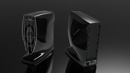
Steven, it looks very cool. Being able to use a small signal xo and then separate channels for tweeters and woofers - gives a lot of freedom for tuning the whole thing up the optimal way. I like the concept, the size and the look 
Thank you Valery,
I wish I knew as much about the electrical side as I do on the acoustics side but this thread and keeping my head in some books is helping there. Now I have to shrink all this Slewmaster design down to size.
I wish I knew as much about the electrical side as I do on the acoustics side but this thread and keeping my head in some books is helping there. Now I have to shrink all this Slewmaster design down to size.
Okay,
Here goes the first published picture of my design as it stands today. I might as well get some feedback at this point on the looks. The screws on the tweeter will be gone, this was an early rendering and I will change the way it attaches to the enclosure. the four center screws will have to remain but the others will be gone. The port is going away, would need to be either to long or to small a diameter to be practical and not have chuffing noises from a to small diameter port.
Something like that would definitely need a SMPS 35-0-35v PS running those 2 SMD OPS's I described. Those OPS' would just need 4 MT-100 devices
for 40W X 2.
If you are trying to make the sub more compact , SMPS might be the way
there as well.
PS - Or just put all 5 amps in the sub , that would allow for a unified protection (5 fet relays).
Here , you would need 15-0-15 , 35-0-35 and >50-0-50V (sub / satellites/control-EQ).
On my sub , I'm using my 15-0-15V for both Val's protection and the sub EQ.
You might want to wait till me and Jwilhelm finish the subs (we will perfect it).
I'd use a simple CFA-X type IPS for your satellites , as well.
OS
Last edited:
Os,
With no sub the speakers I just showed will hit 35hz. Yes you can add a sub but in normal use not listening to movie soundtracks not necessary in the least. They will make your cloths move, believe it or not. The motor on the bass/mid has a 1 1/4 long gap, the surround is limiting the movement, something I plan on addressing with something never seen before. The driver has a 1 1/2" voicecoil and will handle 150 watts, problem right now is you hit the end of the surrounds physical length long before anything else will fail, the only problem with the design to overcome. Right now the p-p movement is about 3/4" before it will bind the surround with full tension. I am serious when I say you can barely stay in the room at full output, as it is now, they are very loud. All the development was done with a round cone in a standard metallic frame and I have only changed the shape of the cone to the elliptical shape you see now. These are like nothing ever done before, not a clone of anything else but over 20 years of development. I need to finish this before I get to damned old to care!
This design has no normal frame, the frame is part of the molded enclosure and has very little surface area to affect the rear of the cones air movement. There are 9 piece of MGOe 52 Neodymium magnets in there and there is both a radial and axial magnet section. I have pushed the linear motor as far as you can, I have stayed on top of Neo development and when the energy goes up I will go up with that. Because it is a very long linear gap motor it does not act like any speaker you have ever heard before. Of course to do that I had to give up max efficiency to make the most linear design I could do. The overall diameter of the motor assembly is only 3" but very deep. Lots of high grade magnets and steel in that motor. No cheap Chinese 1010 steel in this design, electrical steel is the only thing that will handle the flux density. I have done the magnetic analysis of flux path and eddy current and there is a full length Faraday sleeve. This is no toy, I am trying to shake up the market with this design.
ps. The prototypes were used to mix the final soundtrack for one of the Superman movies and a few other albums. A friend who was the VP of music development at Disney had a pair at the studios. They were the only speakers allowed in the facility that weren't by Sony, they had an exclusive deal for all internal speaker systems. When he left there he took them out. I have some pairs out there that have been running for about 20 years now, the only failure was with the tweeters I originally used which I did not make. The design that you see has a 1" Be tweeter that I designed to go with the cone driver. Very different than anything else I have ever seen. Closest thing would be a Revelator and I think my design is better than that.
Last edited:
- Home
- Amplifiers
- Solid State
- SlewMaster Builds