thank you guys for the tips I will let you know how it goes tomorrow is kind of late here in Puerto Rico good night 🙂
If I remember correctly, those drivers run pretty warm. That plate should be of good size.
Right!
finally I see some bias flowing!
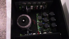
hi guys I'm able to adjust the bias I made a small piece of aluminum for the drivers and the medium power transistor that is part of the bias circuit and finally I was able to adjusted to about 24mV "I just leave it like that" but before that I adjust the pot to maximum resistance the I use the light bulb for initial turn on all look fine and check for everything no smoke all normal fuses were fine all good then I continue by removing the light bulb tester and initiate bias adjustment but since I knew that the amp wasn't not oscillating and I risk a cheap speaker to test audio all was fine no distortion and play music good I let the amp to warm up a bit then I remove the load and do final bias adjustment at the beginning I was not getting noting then I check the resistance of the of the trim pot and was 535 ohms "I think I install a 1K pot" then I begin to slowly lower the resistance and I saw the first 7mV then 21mV etc as I was continue adjusting the pot I then realize that was steady and I left it at 23mV then wait for 15 minutes or more that was on on single resistor but I also check a pair of emitter resistor and I was getting correct reading too after a while I notice that the heat sink was getting warm it was not like that the first time I try so that means that the bias was set about right or close and what I did is just to leave it at 24mV idle I think is fine I then reconnected the speaker and play music for a while really nice sound really detail here are my pictures the quick build of the light dim tester and finally the module and is set now to the next power module to install the power transistors 🙂
supply voltage about 55V DC +/-
audio input my PC
bias adjusted to about 24mV or better say more or less is not perfect
the IPS driver board the Greenamp V1.2 by Ostripper
light bulb cheap and fast 😛
I'm not and engineer or experience guy so what I wrote here is just a common user data experience on this build 😉 I can say my experience was nice really nice 🙂
Best Regards
Juan
Attachments


Last edited:
Did we? Darn!
-Chris
What do you mean Chris?
Do you expect Pete come back?
Hi thimios,
Yes, actually I did. I was hoping for the best.
-Chris
Hi Chris, i Wish!

I will keep my soldering iron hot.
Last edited:
I can say my experience was nice really nice 🙂
Great job Juan! Beautiful build.
Hope you go further on and turn it into a fully built device - this amp deserves a good chassis 😉
Cheers,
Valery
P.S. One more recommendation - OPS power wiring (PSU, binding posts) - it's ok "as is" for a test, but in the real "product", for the best results, you need the wires roughly 5 times "fatter" than the ones in the picture.
thank you Valery yes I got some wires to order question what size gauge? I was thinking 14 gauge for the supply to power boards
oh yes thank you all 🙂
Last edited:
Good job Juan! That woofer needs some sort of baffle. You'll never hear the bass like that.
thank you
oh yes I know I know is just that I don't have a box made for the woofer 🙂
So someone forgot the heatsink 🙄
Slewmaster - CFA vs. VFA "Rumble"
I'm sure that you will enjoy this amp!
Slewmaster - CFA vs. VFA "Rumble"
I'm sure that you will enjoy this amp!
guys finally after a long time I purchase a chassis "from diyaudio.com store"for my build now I'm looking for a circuit to activate by a temporary push bottom switch to activate a relay instead of a toggle switch you guys know a circuit or a section of diyaudio that have that?
Last edited:
That can easily be done with a microcontroller. Our 21st Century Protection system has that option. How to build a 21st century protection board
after so many years finally I will get a complete amp
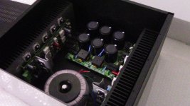
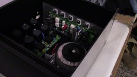
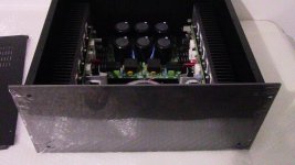
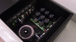
hi guys I finally after so many years on diyaudio all over the place learning from many designs here I got the chassis that I need for the Slewmaster 5P OPS with the Greenamp IPS circuit V1.2 PCB V1.1 now I can say that for the first time I will have a complete audio amplifier with speaker protection soft-star and one that is missing is the turn on circuit using a 12V halo switch that PCB I need to order I apologize for the bad image photos I was so exited that I took them not thinking about lightning the chassis is from diyaudio. com store Pesante 5U really nice chassis 🙂
hi guys I finally after so many years on diyaudio all over the place learning from many designs here I got the chassis that I need for the Slewmaster 5P OPS with the Greenamp IPS circuit V1.2 PCB V1.1 now I can say that for the first time I will have a complete audio amplifier with speaker protection soft-star and one that is missing is the turn on circuit using a 12V halo switch that PCB I need to order I apologize for the bad image photos I was so exited that I took them not thinking about lightning the chassis is from diyaudio. com store Pesante 5U really nice chassis 🙂
Attachments
Last edited:
- Home
- Amplifiers
- Solid State
- SlewMaster Builds