Time to start the design of the next SLAPS application.
This time I want some more power to drive the bass speakers in my four-way setup.
The speakers are Acoustic Elegance TD15H, so they are relative high efficient at 94 dB/ 1 W.
Desired frequency range is roughly 20 Hz to 1000 Hz and desired output power is roughly 40 W.
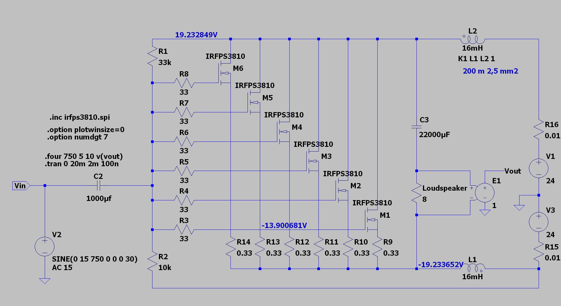
I got this first suggestion from Circlomanen:
Distortion according to the LTSpice simulation is -68 dB for second harmonic and -80 dB for third at 60 Vpp over 8 ohm, that is 56 W.
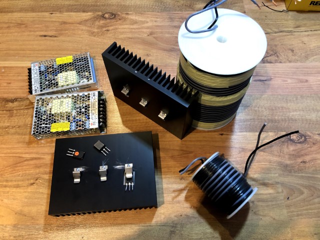
First I need to wind a bifilar coil...
This time I want some more power to drive the bass speakers in my four-way setup.
The speakers are Acoustic Elegance TD15H, so they are relative high efficient at 94 dB/ 1 W.
Desired frequency range is roughly 20 Hz to 1000 Hz and desired output power is roughly 40 W.
I got this first suggestion from Circlomanen:
An externally hosted image should be here but it was not working when we last tested it.
Distortion according to the LTSpice simulation is -68 dB for second harmonic and -80 dB for third at 60 Vpp over 8 ohm, that is 56 W.
First I need to wind a bifilar coil...
Unlike high frequencies, bass frequency requires damping factor . If bass reflex, at least DF of 10 .
Unlike high frequencies, bass frequency requires damping factor . If bass reflex, at least DF of 10 .
The woofer is in a closed box with an internal volume of 140 liter.
What dampening factor do think that this amplifier has?
I tried to sim. Each IRFPS swallowing 16.6A , is it normal? Adjusting R1 86k to have 0.27A for each I get 1 ohm impedance for each , so DF is ok.
Last edited:
I tried to sim. Each IRFPS swallowing 16.6A , is it normal? Adjusting R1 86k to have 0.27A for each I get 1 ohm impedance for each , so DF is ok.
No, it should be around 1 A for each leg with the values given above.
Do you have the right SPICE model for IRFPS3810?
I downloaded it from Infineon . You need 40W/8ohm, why to bias 6A? I simulated also with low cost IRFZ44 (1.2$ /10) it works ok. For the best ,to my opinion is FQA28N15 , but no spice model . As you need only for low frequency, you can use power supply EI magnetics to make the 16mh inductors.
.SUBCKT irfps3810 1 2 3
**************************************
* Model Generated by MODPEX *
*Copyright(c) Symmetry Design Systems*
* All Rights Reserved *
* UNPUBLISHED LICENSED SOFTWARE *
* Contains Proprietary Information *
* Which is The Property of *
* SYMMETRY OR ITS LICENSORS *
*Commercial Use or Resale Restricted *
* by Symmetry License Agreement *
**************************************
* Model generated on Jan 31, 02
* MODEL FORMAT: SPICE3
* Symmetry POWER MOS Model (Version 1.0)
* External Node Designations
* Node 1 -> Drain
* Node 2 -> Gate
* Node 3 -> Source
M1 9 7 8 8 MM L=100u W=100u
.MODEL MM NMOS LEVEL=1 IS=1e-32
+VTO=4.80366 LAMBDA=0 KP=47.7689
+CGSO=5.68964e-05 CGDO=1e-11
RS 8 3 0.003098
D1 3 1 MD
.MODEL MD D IS=1.78525e-11 RS=0.00264568 N=1.05258 BV=100
+IBV=0.00025 EG=1.2 XTI=4 TT=1.99993e-05
+CJO=5.3813e-09 VJ=4.46399 M=0.792399 FC=0.1
RDS 3 1 1e+06
RD 9 1 1e-06
RG 2 7 3.18208
D2 4 5 MD1
* Default values used in MD1:
* RS=0 EG=1.11 XTI=3.0 TT=0
* BV=infinite IBV=1mA
.MODEL MD1 D IS=1e-32 N=50
+CJO=7.02958e-09 VJ=2.86651 M=0.9 FC=1e-08
D3 0 5 MD2
* Default values used in MD2:
* EG=1.11 XTI=3.0 TT=0 CJO=0
* BV=infinite IBV=1mA
.MODEL MD2 D IS=1e-10 N=0.4 RS=3e-06
RL 5 10 1
FI2 7 9 VFI2 -1
VFI2 4 0 0
EV16 10 0 9 7 1
CAP 11 10 1.2698e-08
FI1 7 9 VFI1 -1
VFI1 11 6 0
RCAP 6 10 1
D4 0 6 MD3
* Default values used in MD3:
* EG=1.11 XTI=3.0 TT=0 CJO=0
* RS=0 BV=infinite IBV=1mA
.MODEL MD3 D IS=1e-10 N=0.4
.ENDS irfps3810
I downloaded it from Infineon . You need 40W/8ohm, why to bias 6A? I simulated also with low cost IRFZ44 (1.2$ /10) it works ok. For the best ,to my opinion is FQA28N15 , but no spice model.
I need to get to the triodicity part of the MOSFETs.
Otherwise distortion will be very high.
SLAPS is more or less the bifilar coils with no core material.As you need only for low frequency, you can use power supply EI magnetics to make the 16mh inductors.
6 amps at 50 volts bias is 600watts ( for stereo) dissipation! To get 40 watts out. Did I miss something? Those heat sinks are too small. Youll need a huge power transformer. And you wont need a heater for your room.
Last edited:
6 amps at 50 volts bias is 600watts ( for stereo) dissipation!.
That's correct, 300 W per channel.
Those heat sinks are too small.
I can always add a heat sink or two.
That's two Meanwell LRS-150-24.Youll need a huge power transformer.
It'll be okay with the heat now during the winter.And you wont need a heater for your room.
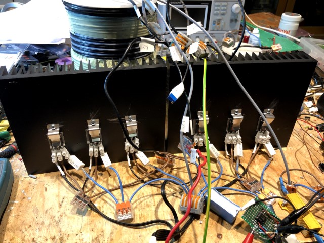
Well, the heatsinks sure gets hot. I will probably have two MOSFETs on one in the finished SLAPS:
The amplifier behaves as expected up to a few watts; less than -60 dB 2nd and less that -80 dB on 3rd.
But with increasing input levels, the 3rd rises as passes the 2nd harmonic.
I have had problems with this before and I think it is my measuring setup that cannot cope with the higher levels. I suspect some ground loops.
I will now tidy up this mess and put together two proper amplifiers and measure over speakers instead.
Great to see some progress! Have you been able to have a listen with the amp driving your midbass speakers yet? I am curious as to the real life sonic difference between normal IRFP054/044 and the "triody" IRFPS3810. I have tested IRFP150, IRLB3813, IRFP7430 and IRLP3034 in this kind of amplifier. Each has its own character, strengths and weaknesses. The IRFPS3810 seems like a good middle of the road device. Much more linear and well behaved then the IRFP7430 but keeping the Triody transfer curves.
The level of distortion is quite dependent on the curves canceling out. The shape and steepness of the transfer curves will vary greatly dependent on temperature, amount of current through each device and the voltage over the devices.
I would recommend you to experiment with decreasing the current though the devices. If you are using 6 paralleled devices per channel then I would recommend you to start with 2,0 ampere current total per amplifier channel. Increase slowly to find the lowest amount of actual measured distortion from the speaker. More current might not equal less distortion, since it all depends on several different distortion-mechanisms canceling each other.
Great to see some progress!

Have you been able to have a listen with the amp driving your midbass speakers yet? I am curious as to the real life sonic difference between normal IRFP054/044 and the "triody" IRFPS3810. I have tested IRFP150, IRLB3813, IRFP7430 and IRLP3034 in this kind of amplifier. Each has its own character, strengths and weaknesses. The IRFPS3810 seems like a good middle of the road device. Much more linear and well behaved then the IRFP7430 but keeping the Triody transfer curves.
Nope, I have not decided if I shall make the current setup portable or build a proper one or two.
The level of distortion is quite dependent on the curves canceling out. The shape and steepness of the transfer curves will vary greatly dependent on temperature, amount of current through each device and the voltage over the devices.
I would recommend you to experiment with decreasing the current though the devices. If you are using 6 paralleled devices per channel then I would recommend you to start with 2,0 ampere current total per amplifier channel. Increase slowly to find the lowest amount of actual measured distortion from the speaker. More current might not equal less distortion, since it all depends on several different distortion-mechanisms canceling each other.
Yes, the LRS-150-24 has a range of 20 to 30 V so that will be an easy test to do. Bias is already via a potentiometer.
According to the simulations I cannot go as low as 2A in total, but that is easily verified.
Problem is with the opamp for the higher voltages, I currently supply it with +/- 12 V but 7815/7915 are on their way in.
Well, with supply voltages at +/- 30 V I get MOSFET failures.
Max Vds is 100 V, so with coil load that voltage is exceeded.
I better stick to a safer +/- 24 V.
The distortion rises dramatically at input voltages above 2.5 Vrms.
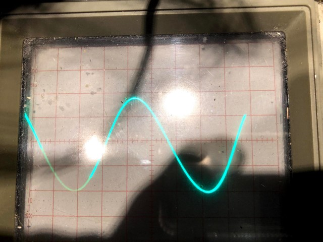
Looking at the output sine waveform, the negative part clips.
That is,the the negative part of the sine wave folds back.
Something like this:
Max Vds is 100 V, so with coil load that voltage is exceeded.
I better stick to a safer +/- 24 V.
The distortion rises dramatically at input voltages above 2.5 Vrms.
Looking at the output sine waveform, the negative part clips.
That is,the the negative part of the sine wave folds back.
Something like this:
Code:
\            /
 \          /
\_/\_/I would guess that you have the polarity of one of the coil windings reversed. This will make the amp clip at very low power levels.
60 Volts from the powersupplies (+-30 volts) will easily exceed the 100 volt drain to source rating of the device.
60 Volts from the powersupplies (+-30 volts) will easily exceed the 100 volt drain to source rating of the device.
I don't think so because that was the first thing I tested.
But I will recheck when I get home from work.
But I will recheck when I get home from work.
Nope, all wiring was correct.
But I could confirm that it is my sound card (EMU 0204) that is the culprit here.
Looking at the waveform with an oscilloscope I see no clipping until when it is supposed to happen.
I can still use the sound card as a generator but as soon as I plug in the ADC input I get heavy distortion.
I guess that I have to rely on the oscilloscope when I dimension supply voltage and gate voltage.
So at +/- 24 V and with a total Id of 5A, I get 18.3 Vrms over 8 ohms before clipping.
And then it is the opamp supplied with +/- 15 V that clips at half that voltage as the amplification is two times.
With 4x470 uF output capacitors I get 17.7 Vrms at 100 Hz and 15.3 Vrms at 50 Hz.
I guess that is enough as I have subs below 100 Hz or so anyway.
And I'm quite satisfied with 42 W.
High time to make a listening test and also do some measurements with a microphone.
I could lower the power supply to +/- 22 V without any clipping and still get 18.3 Vrms output.
Total Id current were 4 A but with a large spread for the individual Id; 0.5 A to 0.8 A.
I guess I have to get a better matching circuit.
Total Id current were 4 A but with a large spread for the individual Id; 0.5 A to 0.8 A.
I guess I have to get a better matching circuit.
I've tried to put the other SLAPS coil in series with no visible effect.
(Of course I increased the power supply to +/- 24 V.)
I've tried to increase the bias with no visible effect.
At 200 Hz I can get 42 W without a distorted sine wave and no clipping, but below 200 Hz the input has to be dropped to not get a distorted sine wave as output,
100 Hz gives 32 W,
80 Hz gives 28.9 W,
63 Hz gives 22.1 W,
50 Hz gives 14.8 W,
40 Hz gives 10.6 W,
31.5 Hz gives 6.7 W,
25 Hz gives 4.5 W and
20 Hz gives 2.9 W.
I can for sure have a HP filter from 200 Hz, but I would like to have "full throttle" at least to 40 Hz as I want to be able to use my bass speakers without the need of separate subs.
- Home
- Amplifiers
- Solid State
- SLAPS for bass.