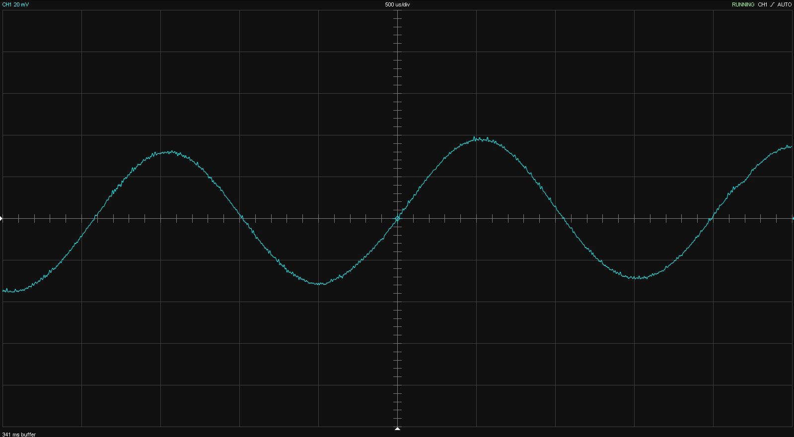
> But at 20 Hz it looks like this
Insufficient inductance. (What is your coil? Have you measured it?)
Your video link does not work "404. That’s an error. The requested URL was not found on this server. That’s all we know."
Insufficient inductance. (What is your coil? Have you measured it?)
Your video link does not work "404. That’s an error. The requested URL was not found on this server. That’s all we know."
> But at 20 Hz it looks like this
Insufficient inductance. (What is your coil? Have you measured it?)
I have suspected that, but putting two coils in series doesn't make any visual effect. Unless the inductance is way too insufficient.
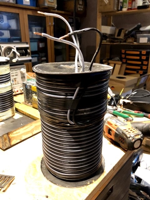
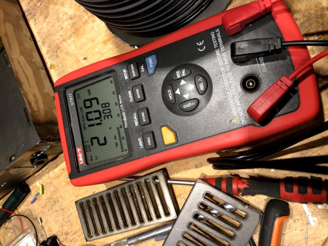
I have now measured the coil in two ways - using a LCR-meter and measuring with a resistor in series.
The DC resistance of the coil is 1.3 ohms.
Both methods indicate as inductance around 3 mH.
That's far from what the coil calculator says (18 mH), but I guess the real coil isn't ideal as the wire's diameter varies a lot (60 to 130 mm) and are not tightly wound because of the insulation.
The wire diameter is 1.8 mm and I've estimated the number of turns to be 265 for the 100 m cable.
>
Your video link does not work "404. That’s an error. The requested URL was not found on this server. That’s all we know."
Here's the clip put on Youtube.
So is a too low inductance the culprit here?
What is the target inductance in that case?
What design parameters should I think about when it comes to increasing the inductance with an iron core?
What about saturation and frequency range?
What is the target inductance in that case?
What design parameters should I think about when it comes to increasing the inductance with an iron core?
What about saturation and frequency range?
I drilled out the coil former and shoved a couple of steel bars in the hole:
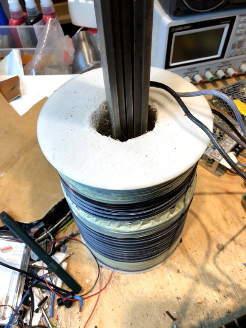
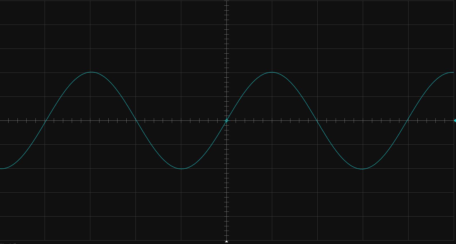
With this core I can get to 13 Hz without visible distortion.
It even looks okay at 20 kHz, so I guess that this is the way to go.
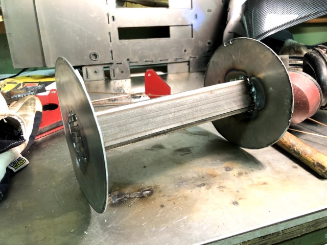
The question now is if I shall make new coils around eight of these 5 by 40 mm steel bars or be satisfied with the current coil (of course with the bars cut off at the coil end)?
With this core I can get to 13 Hz without visible distortion.
It even looks okay at 20 kHz, so I guess that this is the way to go.
The question now is if I shall make new coils around eight of these 5 by 40 mm steel bars or be satisfied with the current coil (of course with the bars cut off at the coil end)?
The coil has now roughly an inductance of 9 mH.
I will rewind the coils around the steel core mentioned above.
Is it better to have the coil gables in steel instead of the current plastic?
I will rewind the coils around the steel core mentioned above.
Is it better to have the coil gables in steel instead of the current plastic?
Just measured with REW and UMIK-1 at 10, 20 and 100 cm distance and at power levels 2 W and 7 W (higher than that and the UMIK-1 clipped).
There was no significant difference between the SPL nor distortion from 20 Hz to 1000 Hz comparing the Trimodal with SLAPS.
There was no significant difference between the SPL nor distortion from 20 Hz to 1000 Hz comparing the Trimodal with SLAPS.
I finally got my measurement circuit to work.
After the DC-blocking capacitors in the measurement circuit I of course must have clamping resistors.
Otherwise the potential will rise above what EMU0204 can cope with.
75 ohm to ground on both legs did the trick (EMU's input floating).
So now I have measured distortion with REW up to 40 W ofgoutput power, that's when SLAPS starts clipping.
Stepped sine 20 Hz to 1000 Hz, above 1000 Hz the distortion increases.
Do you hear any difference between your old Trimodals and the Slaps when driving your bass loudspeakers?
The difference was startling when comparing amps driving your AMT panels.
The difference was startling when comparing amps driving your AMT panels.
Do you hear any difference between your old Trimodals and the Slaps when driving your bass loudspeakers?
The difference was startling when comparing amps driving your AMT panels.
I must build at least one more of these first.
But I want them to be in a box.
Later I will build one per sub as well

I built a box for the SLAPS for bass a while ago, but I haven't managed to get the amplifier stable.
First the operational amplifier blew.
After some faultfinding I concluded that it needed to have its own power supply and not just a 7815/7915 couple after the Meanwell SMPSs.
I don't know if it is the SMPSs or the coils "kicking back" after power off that caused the operational amplifier to blow.
Anyway, with an external power supply the it works.
Second I had problem with individual MOSFETs that were getting really hot.
As I thought that it was a matching problem, I re-matched all the MOSFETs.
It got a little better, but some MOSFETs were always prone to runaway.
Then I noticed that it was always the middle of the three MOSFETs on the heat sink that failed; the heat wasn't evenly dissipated and the heat sink thus to small. So the Vgs dropped leading to even more power through that MOSFET leading to failure.
The two other MOSFETs on that heat sink also "ran away" a little bit and that lead to that the three MOSFETs on the other heat sink got lower Ids.
So having three heat sinks with two MOSFETs seems to have solve that problem.
But thirdly I have a resonance at 54.4 Hz. It is obviously the SLAPS coil that is the culprit; there are high mechanical resonance at that frequency as well.
I've tried to change the PSU's capacitors to double the value but with no change in amplitude or frequency of the resonance.
Even disconnecting the dummy load and thus removing the output capacitors didn't help.
Any ideas on the third problem?
Neither increasing the input capacitor (C2) nor removing the power coils (L3 and L4) made any difference.
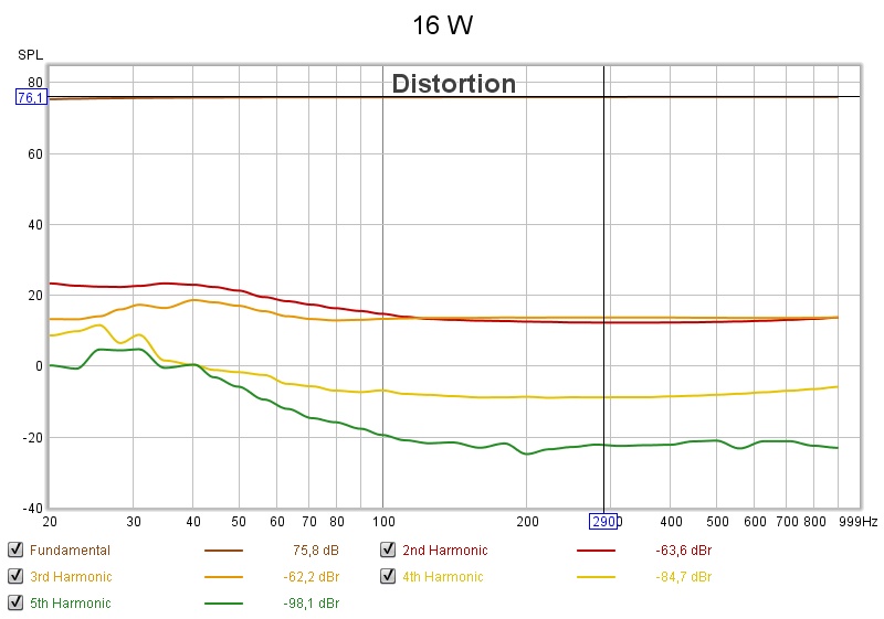
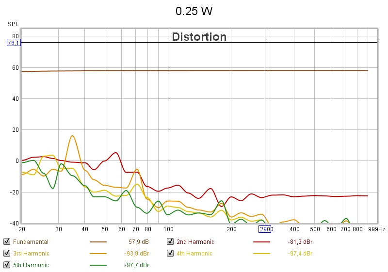
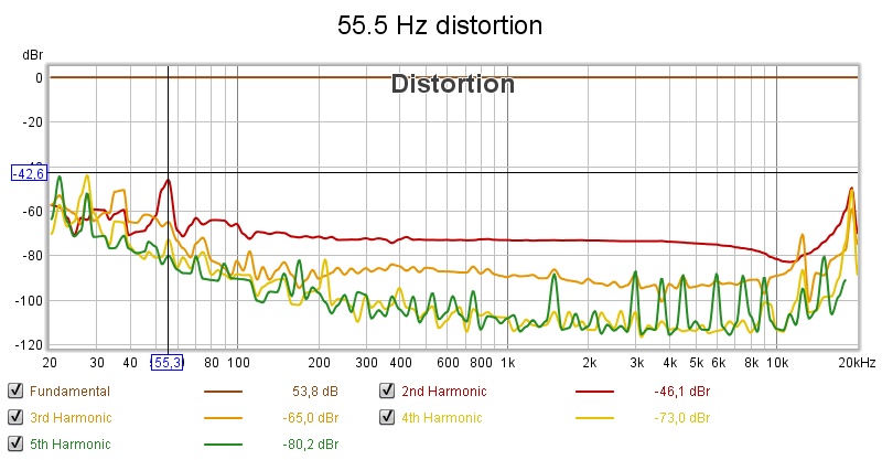
Stepped sine measurement at 16 W output power:
The 55 Hz 2nd order harmonic is clearly visible, but there is also a 4th order at half that frequency:
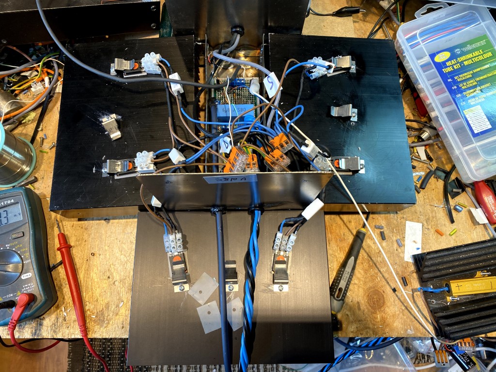
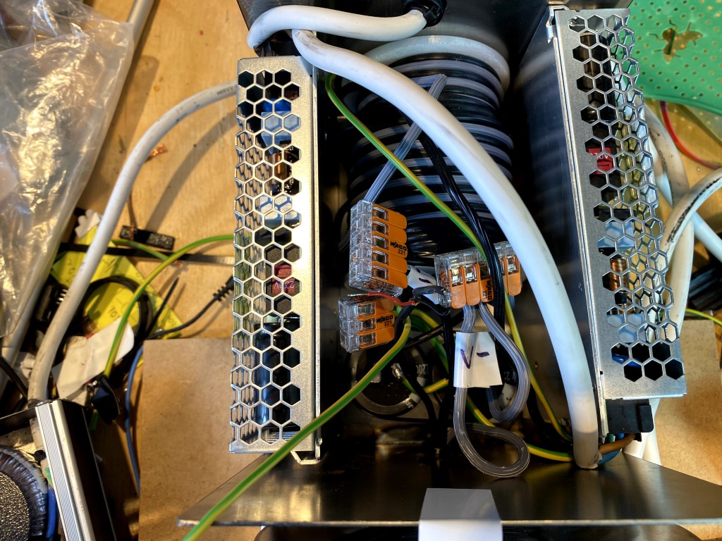
Here are some other pictures of the current contraption:
Whole box with heat sinks dismounted:
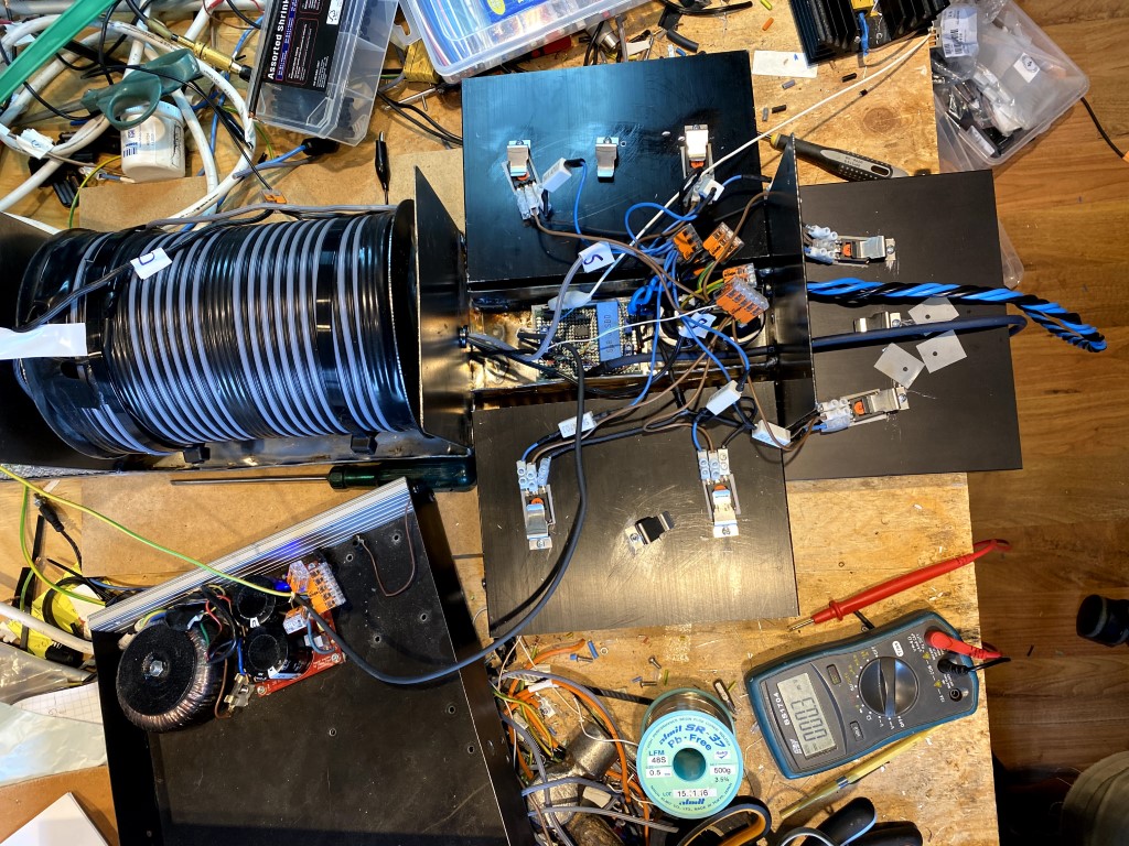
In the lower left is the external power supply to the opamp.
Close up of the heat sinks:
Opamp board:
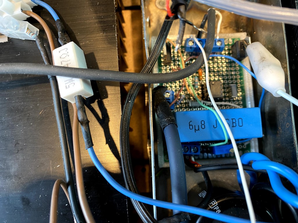
PSU:
An externally hosted image should be here but it was not working when we last tested it.
Stepped sine measurement at 16 W output power:
The 55 Hz 2nd order harmonic is clearly visible, but there is also a 4th order at half that frequency:
An externally hosted image should be here but it was not working when we last tested it.
Here are some other pictures of the current contraption:
Whole box with heat sinks dismounted:
In the lower left is the external power supply to the opamp.
Close up of the heat sinks:
Opamp board:
PSU:
I've doubled the SLAPS coils L1/L2 but there were no changes in amplitude nor frequency.
I've double the DC blocking capacitors in the measuring circuit with the same results.
However, doubling the power coils L3 and L4 reduced the amplitude by 10 dB, frequency still the same.
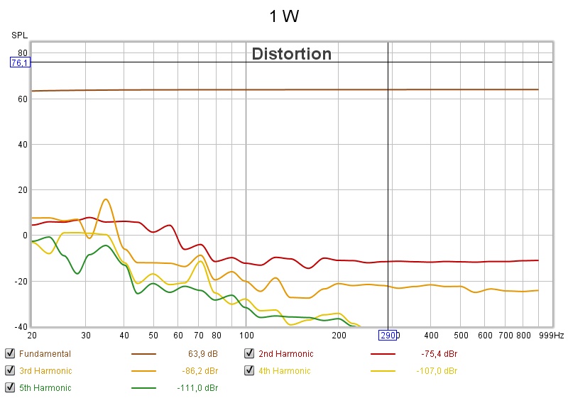
That means while visible at 1 W it drowns in other distortion components at 16 W.
So I guess that the high distortion levels in the low are due to beat frequency residues from the SMPSs.
I've double the DC blocking capacitors in the measuring circuit with the same results.
However, doubling the power coils L3 and L4 reduced the amplitude by 10 dB, frequency still the same.
That means while visible at 1 W it drowns in other distortion components at 16 W.
So I guess that the high distortion levels in the low are due to beat frequency residues from the SMPSs.
Been digging a little bit more.
There's no higher distortion levels at 55 Hz.
It is a SMPS beat frequency at 110 Hz that of course REW marks as a 2nd distortion of 55 Hz.
So the 110 Hz is present at no signal in.
And yes, it is audible through the loudspeakers.
When I measure for 1 W in output power, I have an input signal of -23 dB.
The 110 Hz frequency beat has a corresponding input level of -60 dB.
However, it fluctuates from that level down 30 dB in a 5 second cycle or so.
The successful countermeasures I have been trying simple has been caught at a lower level of the 5 second cycle.
Changing one of the SMPS changed the beat frequency to 108 Hz.
Here's a video of that cycle.
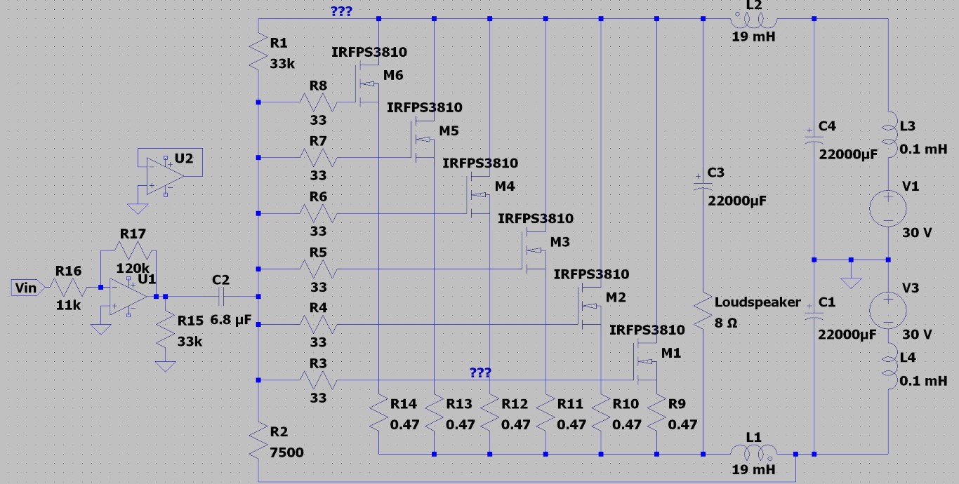
Noisy Cascode configuration
I've temporarily given up on the 3810, the 3rd harmonic is too high.
So I thought that I'll test a cascode configuration instead only to find that the output is very noisy.
If I disconnect V3 (a battery) once the amplifier is live, the noise disappears.
C1 across V3 is not connected, but having it connected makes no difference.
Any ideas?
Attachments
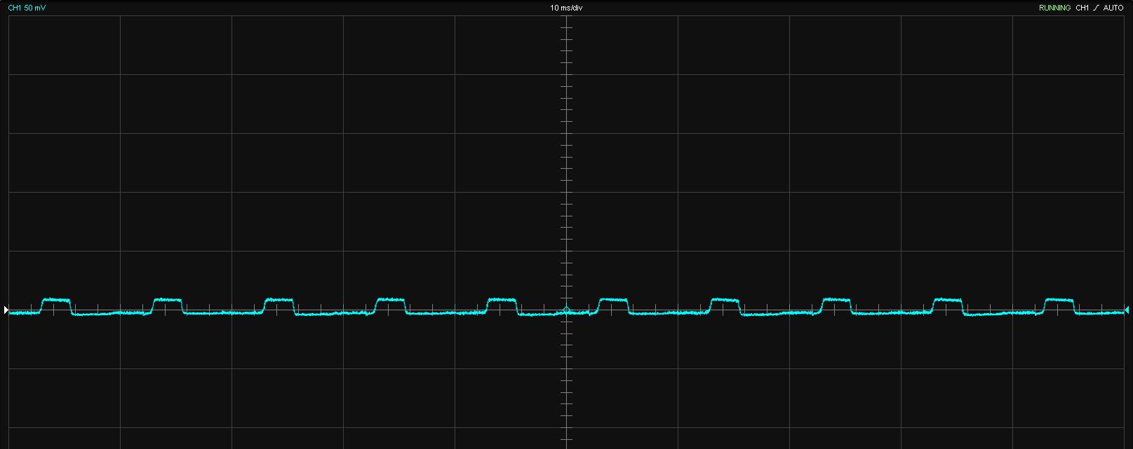
The high noise levels with a 500 Hz input:
If I remove the input signal I can see low frequency noise as well:
And if I disconnect V3:
If I remove the input signal I can see low frequency noise as well:
And if I disconnect V3:
The goal is to have a non-NFB amplifier using the SLAPS forward correction technology.
The SLAPS amplifier has a gain of 2, so a 11x pre-amplifier is required.
It is a class A amplifier by definition since the quiescent current is between 600 mA and 1.6 A for the two types in this thread.
M1 in the cascode variant has a lot more quiescent current as it is the sum of M2 to M5.
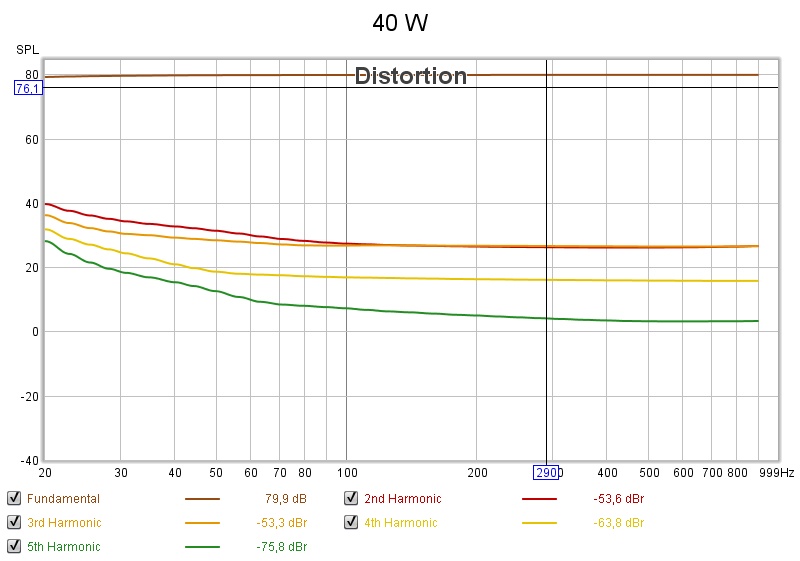
Since the intended woofers has a 94 dB/W/m sensitivity, the desired output power is roughly 40 W at second and third harmonics levels below -60 dB and -75 dB respectively.
I'm barely there with the variant in the first post and not at all there with the cascode variant even if I should solve this noise problem.
The SLAPS amplifier has a gain of 2, so a 11x pre-amplifier is required.
It is a class A amplifier by definition since the quiescent current is between 600 mA and 1.6 A for the two types in this thread.
M1 in the cascode variant has a lot more quiescent current as it is the sum of M2 to M5.
Since the intended woofers has a 94 dB/W/m sensitivity, the desired output power is roughly 40 W at second and third harmonics levels below -60 dB and -75 dB respectively.
I'm barely there with the variant in the first post and not at all there with the cascode variant even if I should solve this noise problem.
Circlomanen already had the answer in the SLAPS for SLAM thread:
So I abandon the cascode for now.
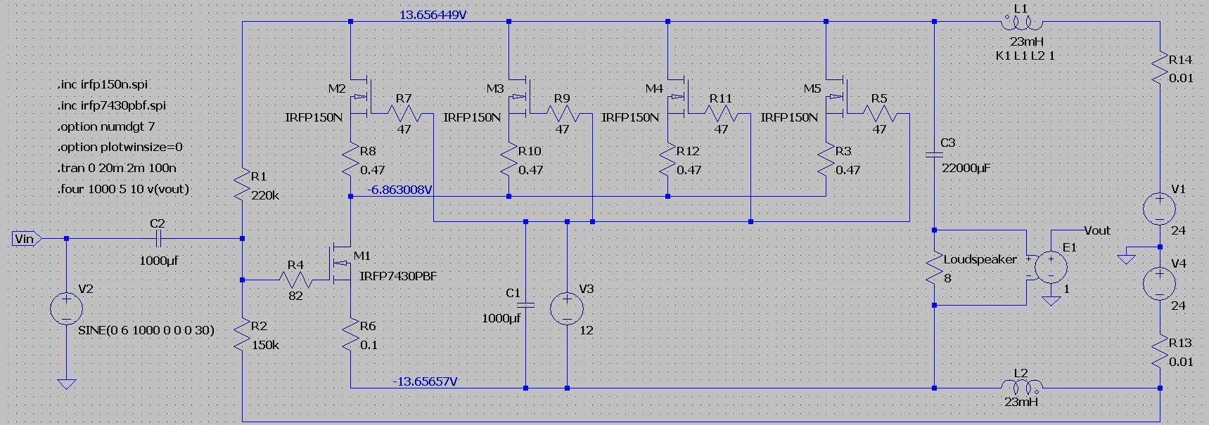
Testing IRFP150 instead of IRFPS3810 (in the amplifier in the first post) looks promising:
The cascoded version is meant as a potential future way forward if you want to experiment with some wild ideas.
Casoding does change the sound character quite a bit.
But there are some pitfalls to.
Cascoding can be prone to HF-instabilities which can be hard to detect in steady state measurements.
So I abandon the cascode for now.
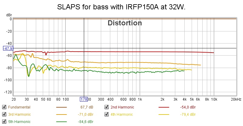
Testing IRFP150 instead of IRFPS3810 (in the amplifier in the first post) looks promising:
SLAPS with JFET
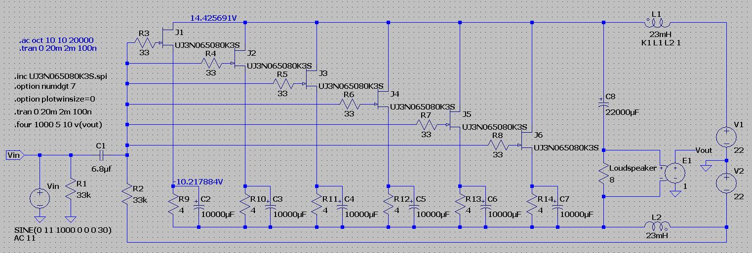
So I will probably go for the IRFP150s, but before the final decision I'd like to test the silicon carbide JFETs that Circlomanen suggested:
According to the LTSpice simulation I can get 32 W at -62/-77 dBs second/third harmonics distortions.
But let's check the reality...
So I will probably go for the IRFP150s, but before the final decision I'd like to test the silicon carbide JFETs that Circlomanen suggested:
An externally hosted image should be here but it was not working when we last tested it.
According to the LTSpice simulation I can get 32 W at -62/-77 dBs second/third harmonics distortions.
But let's check the reality...
- Home
- Amplifiers
- Solid State
- SLAPS for bass.