45,
Thanks!
1. I looked at the link of the Edcor 5k 25 Watt SE transformer.
By default, it showed a 4 Ohm secondary, but of course it also has 6, 8, and 16 Ohm versions.
Please measure the DCR of your 5k primary.
Then please measure the DCR of your secondary.
What are the DCRs of the primary and of the secondary?
And, which secondary impedance does your transformer have?
2. You mentioned measuring the 2nd Harmonic at 100Hz, 1kHz, and 10kHz, that is very good!
(10kHz is the highest frequency that has a 2nd Harmonic within the 20 to 20k audio range).
I own lots of different models of loudspeakers. But none of them have a narrow impedance range of 5 Ohms to 8 Ohms from 20-20kHz.
And, a pure resistive load is very different from the widely ranging impedance, including resistive and Elliptical Load impedances from a single model of loudspeaker.
It is not just how much lower the 2nd Harmonic is with driver stage to output stage partial cancellation; It is more about how the cancellation varies with live music versus the medium to large change of a loudspeaker's impedance versus frequency.
3. Yes, I agree, listening is a very important part of testing amplifiers. I listen to them on a wide variety of different loudspeaker models, and on a wide variety of music.
I am sure you have a really good sounding playback setup(s).
Happy listening!
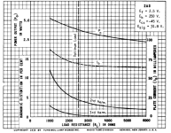
I attach a picture taken from the TungSol 2A3 datasheet than explains things better than any words. Here you can see that 2nd harmonic is present in non-negligible amount for ANY load. I would say that has an asymptotic behaviour for higher values of anode load. It doesn't get less than 2%, that is about half of 2H for the optimal load, while the output power is just less and less.
On the other end, a nice linear DHT or a 6SN7 just needs to work as it should. At high high signal level their natural 2H will cancel out with that of the power tube.
I actually had good luck with the combination of E80CC+2A3. I still have my notes can give you all the details of really simple and basic SE amp if wanna try.
Attachments
Last edited:

This design you reference (the 'WE91 for 1992' or 'Angela 91') is from Joe Roberts circa 1992 when it was published in sound practices. It is not the original WE91 circuit.I don’t understand the sentiment that a 6SN7 isn’t beefy enough to drive a 300B. The tube was designed to be driven from a high gain pentode. The Angela 91 is almost a direct copy of the original WE circuit and uses a 6SJ7.
The 300b was introduced by Western Electric to amplify telephone signals way back in 1938. The original circuits look like typical telephone line amplification circuits of the day and use lots of transformers (input, interstage, output, etc.).
If you want to use cascode 6SN7 to drive 300B like in the schematic posted here then I have no problem with that. I never did.
I am Sorry that I mentioned that with only 4mA current and high output impedance, cascoded 6SN7 would not be a great performer in driving 300b. That was my experience with low current high impedance circuits driving 300b - even ones with large voltage swings.
And I am sorry I tried to provide some ideas on how to make this circuit a better performer too. The mosfet follower has been used by many others before me, such as Tubelab (George).
I like cascodes and have used them in other circuits where they perform very well and their shortcomings are not important. You can use a cascode 6SN7 in a phono stage, for example. That is quite interesting.
Last edited:
Thanks for posting this. I'm sure this design goes back to the 1940's. I believe it was used in movie theaters.
6A3sUMMER, my CXSE25-8-5K measures:
Primary - 82.5 Ohms
Secondary - 0.3 Ohms
This is the 8 ohm output version of the 5K input SE 25W transformer.
Primary - 82.5 Ohms
Secondary - 0.3 Ohms
This is the 8 ohm output version of the 5K input SE 25W transformer.
If copper loss has been established, add in a similar amount for iron loss to get closer to the bottom line.
If you are over 50 anything above 10 KHz doesn't matter. Unless its a FB amp. 😀
If you are over 50 anything above 10 KHz doesn't matter. Unless its a FB amp. 😀
45,
Thanks for the Graph!
Initially looks pretty good.
When I get the time, I will analyze it a little closer than my initial view.
Thanks for the Graph!
Initially looks pretty good.
When I get the time, I will analyze it a little closer than my initial view.
soulmerchant,
Thanks!
You mentioned one of the main characteristics of the Cascode circuit: High output impedance.
For a resonated RF amplifier, the impedance of the load can be extremely high. How high do you want?
Then use a high Q resonator, and tap it down to the next stage load (use a coil tap, or 2 cap divider, etc.).
That is one reason why you see the cascode in a TV RF amplifier; Ham Receiver, Radar IF circuit, and even in a 10MHz Ultrasound Doppler receiver (like the ones I worked on).
Here is another reason:
Triodes have better noise figures than pentodes. But a triode has a lower plate impedance, that swamps out the resonator Q, which makes the bandwidth too wide (no signal rejection of out of band signals).
So . . . enter the dual triode cascode circuit (boy, those early engineers were genius - again and again).
The Q of an Audio "resonator" does not exist, when it covers 20Hz to 20kHz (Q is much much less than unity in that case; and frankly has no meaning there).
But used carefully, and implemented properly, a cascode circuit can be used to cover the 20-20k bandwidth, and provide certain characteristics and good performance that is useful to audio.
Last edited:
In a SE transformer with DC current and no inversion of the magnetic field H (Bdc > Bac, at all signal levels) core losses are much lower than a PP transformer or power transformer. The presence of the air gap linearizes the hysteresis loop which becomes much narrower. Roughly I would say that loss is easily 10-20 times less. This also one reason why I have always thought that exotic cores, with very low losses, are best used with no DC current (small signal or PP interstage and output transformers). In fact, for example, Jensen defines the insertion loss only based on source resistance, dc resistance and transformer impedance as their transformers do not allow DC current but use mu-metal or similar core. The error is really small and not worth considering.If copper loss has been established, add in a similar amount for iron loss to get closer to the bottom line.
If you are over 50 anything above 10 KHz doesn't matter. Unless its a FB amp. 😀
Before Covid I bought a pair of 300B SE transformers with amorphous core because everyone was swearing that they sound better than those with standard GOSS core. I have tried and to be honest I have not been convinced. They are good but I prefer a good quality GOSS. For the same core size, turns and efficiency OTs with amorphous core have lower inductance which makes the low frequency distortion worse....
Last edited:
jhstewart,
Thanks!
Your total insertion loss estimate sounds like an easy rule of thumb.
I tested at 1kHz:
My latest test of a 5k to 9 Ohm transformer had about 0.69 dB loss due to primary DCR and secondary DCR.
The measured total loss was 1.0 dB.
Close to the estimate.
Of course that does not include any other power reduction due to additional low and high frequency losses.
I always consider those to be bandwidth related losses, not the minimum insertion loss at 1 kHz.
@6A3sUMMER, that's high loss overall.
0.3 dB core loss means that the core is not best quality. A really good core should result in 0.1 dB or less. Or another reason can be that they are using a large core for the task with smaller air-gap (assuming that Bdc > Bac in your tests).
0.3 dB core loss means that the core is not best quality. A really good core should result in 0.1 dB or less. Or another reason can be that they are using a large core for the task with smaller air-gap (assuming that Bdc > Bac in your tests).
Last edited:
TheGimp,
Thanks!
From your data of the Edcor 5k to 8 transformer:
I calculate the part of the insertion loss due to primary DCR and secondary DCR to be 0.46 dB.
That is pretty close to Edcor's data sheet that says insertion loss: 0.5 dB.
Thanks!
From your data of the Edcor 5k to 8 transformer:
I calculate the part of the insertion loss due to primary DCR and secondary DCR to be 0.46 dB.
That is pretty close to Edcor's data sheet that says insertion loss: 0.5 dB.
45,
Thanks!
As always, transformers are all a bag of tradeoffs . . .
Insertion Loss
Bandwidth
Saturation
Distortion
Weight
Price . . .
and more.
A larger core and the same air gap space, can give more power at a low frequency, before it saturates.
Tradeoffs, tradeoffs, tradeoffs
I do not loose any sleep if my output tube puts out 1 dB more power to the primary, than the power the secondary puts out.
Last edited:
@6A3sUMMER, are you measuring the core loss with DC current in it and making sure that Bdc > Bac?
Last edited:
The insertion loss in actual use is a bit less because the source impedance has to be accounted for:TheGimp,
Thanks!
From your data of the Edcor 5k to 8 transformer:
I calculate the part of the insertion loss due to primary DCR and secondary DCR to be 0.46 dB.
That is pretty close to Edcor's data sheet that says insertion loss: 0.5 dB.
dB = 20log [(Rs+RL)/(Rs+RL+Rdc)]
Rs= source resistance (700R for the 300B)
RL= reflected primary resistance (5K)
Rdc=total DC resistance (270R in the case of EDCOR, 82.5R + 25x25x0.3R)
That makes the insertion loss 0.4 dB. Add another 0.1 dB core loss that's what EDCOR claims. 0.5 dB total loss or less can be classified as very good quality.
I measure the bare bones performance of the transformer, with no DC.
I do not purchase a transformer that does not have at least a few particular specifications, including quiescent DC rating.
Then all things can change when I build it into a real amplifier, and see how the complete amplifier performs.
If some transformer characteristic degrades significantly, I will see that because that will cause the amplifier to fall short of my predicted performance.
I am picky about reliability, sound quality, and cost.
I am not creating a fuel turbocharged dragster.
And I am not competing against any commercial amplifier (I do not want to be in business, and I do not have enough Aspirin for that).
Yes, it is nice to consider the loss of the output tube, but . . .
I always said: the Power the output tube puts into the primary.
I did not say the loss of power in the output tube plus the loss of power in the primary DCR.
I am purposely not considering the loss of power in the output tube itself (that gives the transformer's loss, not the tube + transformer's loss).
That means my concept works for high plate impedance pentodes and beam power tubes, and works for medium to low plate impedance triodes.
Transformer loss; or tube + transformer loss.
Generally, a pentode or beam power tube has less internal power loss, versus a triode internal power loss.
Last edited:
Then your measurement is not valid for the transformer in actual use. With no DC current in it, any stationary (sinusoidal, I guess) signal you will apply will result in the inversion of the magnetic field H. When it crosses the zero, the hysteresis loop will have an anomaly, it will be larger and so core loss will be higher.
You could also have a look at distortion, when H gets inverted distortion increases and it looks like saturation but it's not. Just similar spectrum.....that's why the DC induction must be higher than AC induction. This does not happen in gapless (or with very small natural gap) PP transformers but core loss is higher than the equivalent SE.
You could also have a look at distortion, when H gets inverted distortion increases and it looks like saturation but it's not. Just similar spectrum.....that's why the DC induction must be higher than AC induction. This does not happen in gapless (or with very small natural gap) PP transformers but core loss is higher than the equivalent SE.
Last edited:
45,
I already admitted that with DC everything changes.
But you answer before I even finish my re-edit of my posts (which I often do when I re-read them).
I was re-editing my post # 116, after you commented on my post # 116, but I had not read your later comment.
Now you know a reason that I do not like texting on the phone; the other person answers before I am done.
No problem. Just saying that your SE transformer has more likely some 0.7 dB loss in actual use, which is still ok.
Typical classification for output transformers is: loss<0.5 dB is higher quality, 0.5<loss<0.8 average, loss>0.8 lower quality.
Of course, the overall quality is also related to the other parameters: inductance, FR etc....
By the way, to be precise, it is called insertion loss because it's happening upon the insertion of a device (the power tube). The transformer alone would be classified in terms of efficiency or power loss (i.e. 10xlog[efficiency]).
Last edited:
The test curves demonstrate exactly what theory predicts, no surprise. 👍I attach a picture taken from the TungSol 2A3 datasheet than explains things better than any words
- Home
- Amplifiers
- Tubes / Valves
- Skunkie Designs 300B