Wouldn't it be a good idea to mount the thermal sensing transistors in the CCS closer to or between the output mosfets?
D
Deleted member 148505
I think this is ok. Sensors can be mounted alongside with the mosfets.
Size is reduced to 3.05" x 3.875"
Since this is difficult to etch, I'll also give the gerber file once this is finished. 🙂
Size is reduced to 3.05" x 3.875"
Since this is difficult to etch, I'll also give the gerber file once this is finished. 🙂
Attachments

Alongside the outputs is a poor measure of die temperature unless the heatsink is very small. When a large heatsink is used, the device and mounting thermal resistance become very significant.
Bolted on top or glued to the drain lead is the best way
Bolted on top or glued to the drain lead is the best way
D
Deleted member 148505
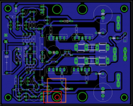
Yes, I changed the layout to make the sensing transistors bolted with the mosfets.
Attachments
Last edited by a moderator:
D
Deleted member 148505
Hi guys, can this amp be designed to drive a very low impedance load (say 0.5 ohms?)
😱
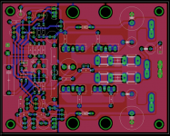
Like my other works, I believe the layout is 100% accurate.
Attached the layout and gerber file. The PDFs and the GERBERs are free for all 🙂
Hi
I hope someone can organise a group buy for the pcb
Thanks for the nice work .
regards
kp93300
Quote:
HiOriginally Posted by jlester87 View Post
Like my other works, I believe the layout is 100% accurate.
Attached the layout and gerber file. The PDFs and the GERBERs are free for all
I hope someone can organise a group buy for the pcb
Thanks for the nice work .
regards
kp93300
What happened to the attachments?
How much power?Hi guys, can this amp be designed to drive a very low impedance load (say 0.5 ohms?)
To drive 0.5R sensibly, the rails would have to be MUCH lower, different output devices as Rds on of 0.5R is too high and reduce the output source resistors to 0.1R or less
This topology works well into low Z loads as it can swing close to rail to rail
Please check my build
Hi,
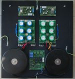
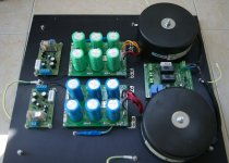
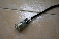
I'm building the GB150D and while I wait for the amplifier pcb's to arrive I started building the power supply section.
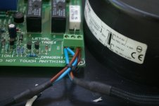
I'd like to ask you if my build looks safe and robust. I'm particulary worried about the transformers connection to the soft-start board and the on-off switch wires.
Does it looks fine?
I attach some pictures.
Thanks! 🙂
Hi,
I'm building the GB150D and while I wait for the amplifier pcb's to arrive I started building the power supply section.
I'd like to ask you if my build looks safe and robust. I'm particulary worried about the transformers connection to the soft-start board and the on-off switch wires.
Does it looks fine?
I attach some pictures.
Thanks! 🙂
Attachments

Last edited:
You can grab a PCB of GB150D on eBay on item : 221279128666
It was made on request of several members.
Ciao!
Do
It was made on request of several members.
Ciao!
Do
You can grab a PCB of GB150D on eBay on item : 221279128666
It was made on request of several members.
Ciao!
Do
I already did,thanks Do! 😀
Just got my set of boards, they are really nice!
Can't wait to start building this amp!
Ciao!
Do
Can't wait to start building this amp!
Ciao!
Do
Just got my set of boards, they are really nice!
Can't wait to start building this amp!
Ciao!
Do
Go for it!

It's a wonderful amp! I'm still waiting for my boards to arrive. 😉
Do,
Are you going to use the zener mod or the RCR? Wich one do you choose and why?
Zener noise maybe be a concern (not sure if it's audible) and the capacitor across the zener can be raised to 10uF to mitigate this.
The RCR mode, in the other hand ,has no zener but only works if the preamplifier impedance is lower than 800 Ohms. May pick some RF noise.
Both mods simulate to a 20dB higher PSRR which is equivalent of 10 x more supply capacitance.
One note about the value of R2:
With the zener mod R2 should be 925 Ohm - Z preamplifier.
With the RCR mod R2 should be 800 Ohm - Z preamplifier, typical 750 Ohms.
Ciao!
Paulo.
Last edited:
Just to let you know that they now have partial kits with matched input/out BJT/MOSFET
Mosfet 150W Power Amplifier GB150D Partial KIT Matched Input OUT BJT Mosfet | eBay
Ciao!
Do
Mosfet 150W Power Amplifier GB150D Partial KIT Matched Input OUT BJT Mosfet | eBay
Ciao!
Do
Are you going to use the zener mod or the RCR? Wich one do you choose and why?
Not sure yet. I will check this after I'm finished with my current amp build.
Ciao!
Do
I ordered a pair of the boards. Sure can't beat that price. I have a few amps to build first but I have wanted to build one of these since Greg first started talking about them.
The link died... Search fleaBay item 321207773670 for the version with matched Mosfets and BJT.
Do
Do
How do you know the devices are genuine? That is what I would worry about. That's why I just bought the boards. At least I will know where the devices I use come from.
- Home
- Amplifiers
- Solid State
- SKA GB150D now public domain...