D
Deleted member 148505
@jlester87
The post I referred to wasn't on this site and my link is dead now. It was the typical IMD 19+20kHz test IIRC. The distortion was mostly 2nd and 3rd harmonic in character with a slight elevation in the 5th order at 150W. The speed of the supply would seem to help this amp so an SMPS should outperform a linear supply if you can avoid the RF and switching noise.
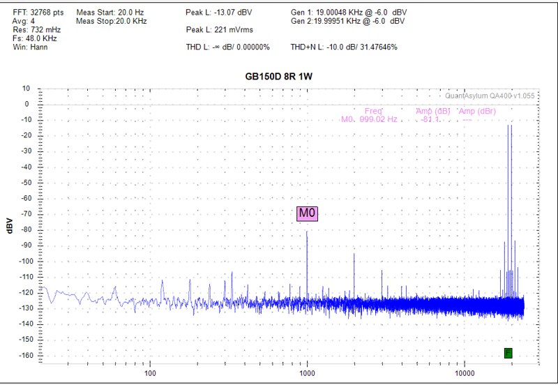
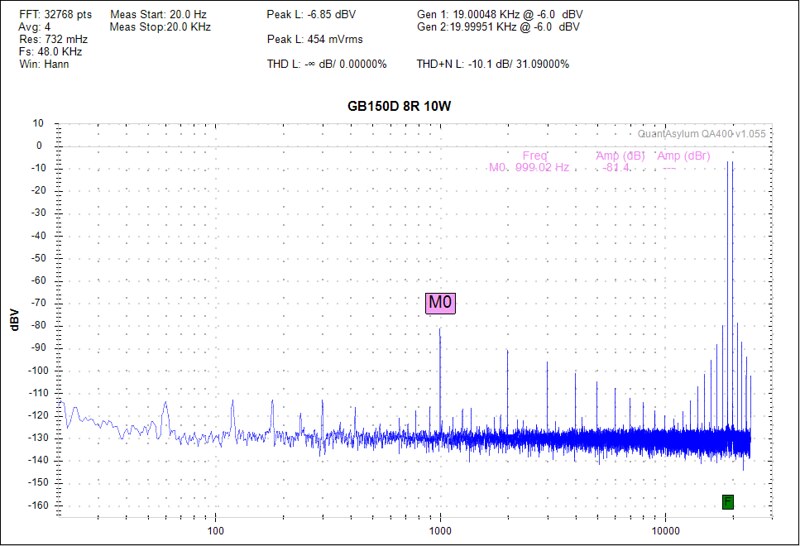
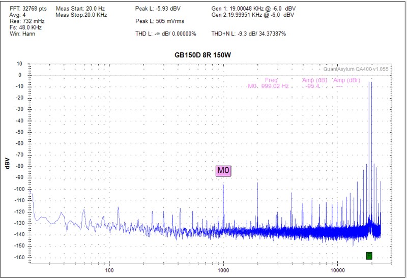
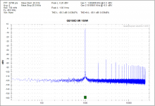
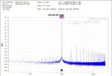
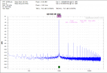
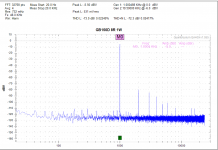
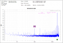
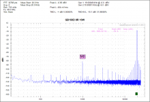
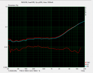
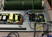
I repeated THD measurements with IMD for 8 ohms load 1W, 10W, 100W, 150W.
QA400 doesn't have IMD calculation, but we can just inspect the 1khz, 2nd order IMD product.
https://www.quantasylum.com/content/Home/tabid/40/Post/213/QA400-IMD-Measurements
The original signal is attenuated to -6dbV for 1W measurement and attenuated to 0dbV for 10W, 100W and 150W measurements, I assume that the IMD mixing product is also attenuated and has the same ratio as the original signal? (correct me if i'm wrong)
Best is 16.98ppm, -95.4dB (150W) and worst is 175.79ppm, -75.1dB (1W) if we only consider the 1khz mixing product...

Attachments

Last edited by a moderator:
Thank you for your answers. 🙂
KSC1845/KSA992 seem to be a good alternative if the E grades can be found.
I really like this amplifier, one of the best I built.
Anyone know of a source for the E grade parts?
Or the BC546/56 in C grade?
Or have better parts been found?
TME, never heard of them or DIOTEC, I'll try to find some history on the company.
Anyone tested any DIOTEC parts?
Anyone tested any DIOTEC parts?
First of all, the difference is subtle but certainly there. Without a good A/B setup, it may not be as noticeable. I have checked it many times against many different amps. Of course, if you built it differently than the designer all bets are off.
Terry, did you try running the GB150 say with .1dB more level than the other amp,
just to see if your preference changes or if it ends up being better? I'm just trying
to get a better understanding of how you did the tests.
Terry, did you try running the GB150 say with .1dB more level than the other amp,
just to see if your preference changes or if it ends up being better? I'm just trying
to get a better understanding of how you did the tests.
The purpose of the "Blind" A/B test is to evaluate the two amps under identical conditions. The two amps are fed by the same input signal with the only difference being attenuation to get output levels identical. Both amps feed the same pair of speakers. A speaker switch is used to switch between amps on the fly. If the amps are not tested at the same level they will always sound different.With the levels matched it is you can hear subtle differences if they exist. Both pair of SKA GB150's that I built, it is clear that the highs are attenuated compared to my other amps. I did use the diode version so I can't say if that is the reason. Some day I may pull it apart and make the changes to see if that has an effect.
Blessings, Terry
Are the two passive input filters set to the same frequencies?
These should define the pass band of all your amplifiers.
These should define the pass band of all your amplifiers.
jlester87
Nice work! What amp bias did you use?
AndrewT
Good point, still4given may also want to check for low hFe on the input pairs to explain the tapered high frequencies.
Nice work! What amp bias did you use?
AndrewT
Good point, still4given may also want to check for low hFe on the input pairs to explain the tapered high frequencies.
Last edited:
D
Deleted member 148505
jlester87
Nice work! What amp bias did you use?
AndrewT
Good point, still4given may also want to check for low hFe on the input pairs to explain the tapered high frequencies.
Thanks, I used 120mA on cold heatsink. The heatsink gets very hot though because it's only L-Bar heatspreader so bias might be actually lower.
I also used 2n5551/2n5401 on all signal transistors for the record..
Member
Joined 2009
Paid Member
The purpose of the "Blind" A/B test is to evaluate the two amps under identical conditions. The two amps are fed by the same input signal with the only difference being attenuation to get output levels identical. Both amps feed the same pair of speakers. A speaker switch is used to switch between amps on the fly. If the amps are not tested at the same level they will always sound different.With the levels matched it is you can hear subtle differences if they exist. Both pair of SKA GB150's that I built, it is clear that the highs are attenuated compared to my other amps. I did use the diode version so I can't say if that is the reason. Some day I may pull it apart and make the changes to see if that has an effect.
Blessings, Terry
I built my own version of this amplifier where I wouldn't expect the differences to result in a different sound signature than the original design. See here: http://www.diyaudio.com/forums/solid-state/239418-tgm7-amplifier-based-greg-ball-ska.html
I also found that the treble is different from my other amplifiers, based on the 'blameless' approach.
I can't say that the treble on this amp is wrong per se, but subjectively it has slightly less 'air' or 'sparkle' to borrow some over-used descriptions. It does however sound very neutral, very very neutral and I've used it a lot.
If I had to choose an amplifier to experiment with the sound of different pre-amps then this one would be my first choice due to its neutrality.
Anyone know of a source for the E grade parts?
Or the BC546/56 in C grade?
Or have better parts been found?
Try https://www.rocelec.com/semiconductor-products-services/
There is a min Total Purchase of $100/
Last edited:
Thanks, Rochester looks very official, have people ordered and are they reliable with regard to fakes?
TME, never heard of them or DIOTEC, I'll try to find some history on the company.
Anyone tested any DIOTEC parts?
Hi Pete,
I've ordered from TME a couple of times without issues.
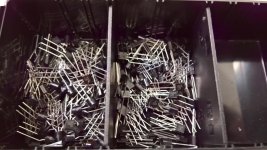
Some time ago I received DIOTEC BC 546C/556C from TME. I did no further testing than Hfe on approx 20 pcs and they were up to spec.
Attachments
I was hoping to build this into an existing chassis where I'd have to wire (4") from
the PC board to the output FETs on the heatsinks. I see that there were stability
issues in the TGM7 design, do I have to worry about adding that short amount of wire?
the PC board to the output FETs on the heatsinks. I see that there were stability
issues in the TGM7 design, do I have to worry about adding that short amount of wire?
JLesterP
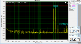
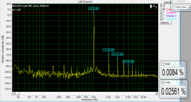
It may be usefull or not but a few years back I have made a board for SKA150, some resaults bellow. The zobel network is very important in this design !! Must be soldered on the board.
Regards
Peter
It may be usefull or not but a few years back I have made a board for SKA150, some resaults bellow. The zobel network is very important in this design !! Must be soldered on the board.
Regards
Peter
Attachments
Thanks Anders good to know. What sort of hfe range did you find?
Hi Pete,
I randomly picked 10 of each gender and measured.
Diotec hfe results at 6 mA
BC546C: 504, 544, 539, 479, 519, 483, 485, 518, 486, 543
BC556C: 528, 566, 508, 542, 463, 488, 560, 539, 497, 536
Last edited:
D
Deleted member 148505
JLesterP
It may be usefull or not but a few years back I have made a board for SKA150, some resaults bellow. The zobel network is very important in this design !! Must be soldered on the board.
Regards
Peter
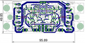
Nice to see similar harmonic profile, which shows why this amp has a "thick" sound.
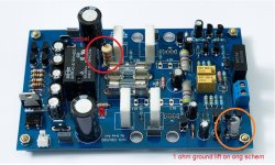
I used onboard zobel, see attached pic, also for the record, I bypassed the 1 ohm ground lift, when I measured the amp..
Regards,
Lester
Attachments
Member
Joined 2009
Paid Member
I was hoping to build this into an existing chassis where I'd have to wire (4") from
the PC board to the output FETs on the heatsinks. I see that there were stability
issues in the TGM7 design, do I have to worry about adding that short amount of wire?
I'm not sure I can remember the details, they are hopefully in the thread. A re-spin of the pcb fixed it perfectly though and the amp has been very stable since then.
What I remember though is that this is an amplifier that has high unity gain bandwidth with loop compensation that doesn't leave too much margin for error as both too little and too much phase lead reduces stability (pcb layout parastics are very important) and that MOSFETs like to oscillate all by themselves so you have two causes for parasitic oscillation before you even start to pay attention to external wiring (grounding in particular). I wouldn't want to try building it with 4" of wires - that's a nice bit of inductance and an antenna you'll have there on those fast FETs. I would suggest though that you might be able to keep it stable with a small R + C at the pins of the devices from gate-to-drain; these local 'zobel' networks help tame the FETs.
fyi - I never experienced what is described above as a 'thick' sound. It is extremely neutral, almost leaning towards 'boring' actually 😀
Last edited:
Normally, the GB150 is reasonably 'standard' gain for a power amp, 28x.
Out of interest, where are you getting your mosfets?
Whoa, just spotted this years later...I meant 28dB. 2013 was a bad year for me.
- Home
- Amplifiers
- Solid State
- SKA GB150D now public domain...