If none of your speakers are shorted by 100nF in the crossover (quite likely), then you can get away with that. Normally this is solved with an output L//R network, but in this case the need for it is arguable.
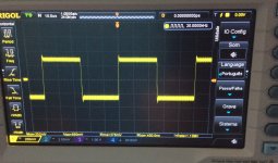
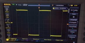
Set your square wave generator so that the square wave at the output of the amp is as low as you can go and still see it well on the scope. Test without the input LP filter and then see how the square wave is affected by the capacitor. It sounds like your amp is working fine. The question left is whether it is still stable at 10A output, and whether that is achievable without any overshoot (sometimes it isn't, especially on amps like this with the output stage parasitics determining the stability).
Set your square wave generator so that the square wave at the output of the amp is as low as you can go and still see it well on the scope. Test without the input LP filter and then see how the square wave is affected by the capacitor. It sounds like your amp is working fine. The question left is whether it is still stable at 10A output, and whether that is achievable without any overshoot (sometimes it isn't, especially on amps like this with the output stage parasitics determining the stability).
It looks harmless to me. Your amp has a slight rise in FR at RF, but this alone does not cause malfunctions. Although many people argue it doesn't sound very good (yet look at the popularity of this very amplifier).
Maybe you can do the same test with the 10pF cap. Then I suggest you listen to both capacitors, and determine which option sounds better. They both seem to give reasonable results in a square wave test.
Maybe you can do the same test with the 10pF cap. Then I suggest you listen to both capacitors, and determine which option sounds better. They both seem to give reasonable results in a square wave test.
Member
Joined 2009
Paid Member
This amp has very fast output devices and a very high unity gain bandwidth, the compensation is not trivial and pcb layout parasitics are a significant influence so the value of the cap specified for the original design is only good when used with the same pcb and parts. It took me 3 tries to get get my TGM7 correct but I'd put it up against anybody's pcb layout for this amp !
Member
Joined 2009
Paid Member
OH golly, I don't remember how the square wave looked. I will have to check my notes or get it hooked up to a scope again (although I don't fancy removing the input rf filter). I have never been one to insist on zero overshoot by the way - I don't mind a bit of overshoot so long as it isn't ringing - very fast amplifiers like this can excite all sorts of things in your test set up if you aren't careful - grounding, wiring and oscilloscope probe tip compensation are all important. I have correlated overshoot behaviour with a little harshness in the treble and I have detected no such character trait with the TGM7.
I would suggest that your scope plot is OK providing the amp is stable when used with your speakers and speaker cables - if they are particularly long / capacitive cables try simulating this with your square wave test by hanging a small cap on the amplifier output in parallel with an 8R load, but be careful - high amplitude square waves into a capacitor is sudden death for most amplifiers even when properly compensated - start with low signal levels and slower square waves. If the amplifier sounds good to you, then I doubt there is an issue.
I would suggest that your scope plot is OK providing the amp is stable when used with your speakers and speaker cables - if they are particularly long / capacitive cables try simulating this with your square wave test by hanging a small cap on the amplifier output in parallel with an 8R load, but be careful - high amplitude square waves into a capacitor is sudden death for most amplifiers even when properly compensated - start with low signal levels and slower square waves. If the amplifier sounds good to you, then I doubt there is an issue.
Last edited:
please could tell me what the modifications in this amplifier to operate at 35 volts, can only use a couple mosfet in output.
Member
Joined 2009
Paid Member
I would think that if you don't ask the amplifier to produce huge currents into a low impedance load, then operating at 50V rails with single pair of outputs is fine.
If you want to use lower voltage then probably you only need to change some resistors to keep the current flow in parts of the circuit at the design level. At first guess, resistor values reduce to 35/50 (ratio of change in rail voltage) and you need to lower R11, R13 (bias for input stage current source), R15 and R17 (bootstrapped current source) plus R24 and R26 for driver stage current. To be honest, I think it would work fine without any changes.
If you want to use lower voltage then probably you only need to change some resistors to keep the current flow in parts of the circuit at the design level. At first guess, resistor values reduce to 35/50 (ratio of change in rail voltage) and you need to lower R11, R13 (bias for input stage current source), R15 and R17 (bootstrapped current source) plus R24 and R26 for driver stage current. To be honest, I think it would work fine without any changes.
Last edited:
D
Deleted member 148505
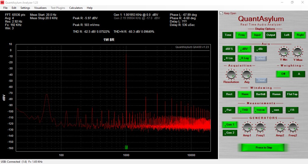
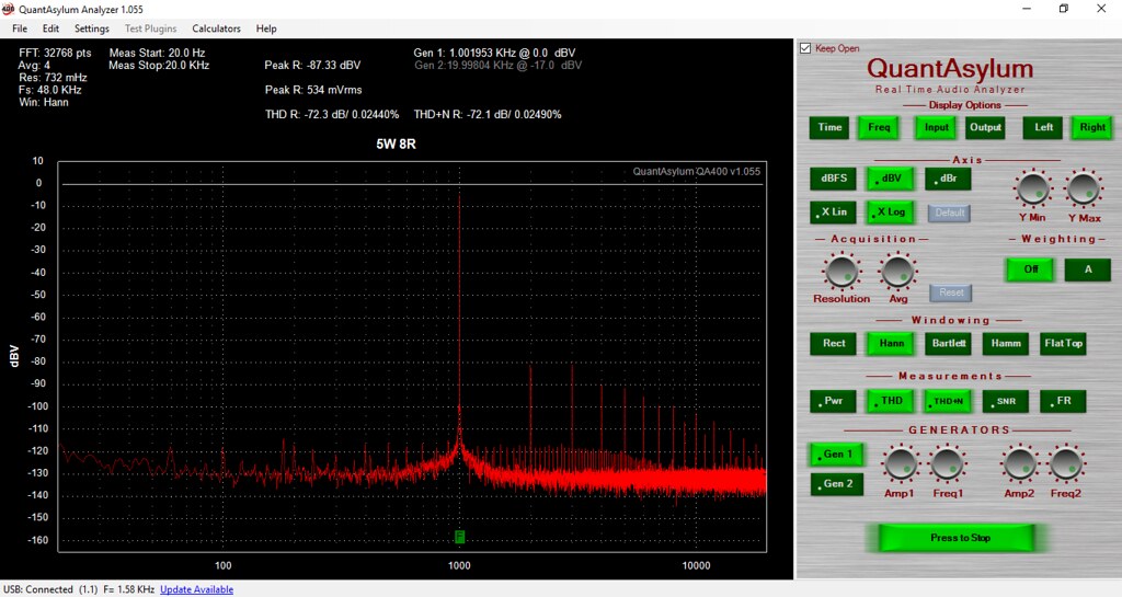
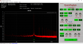
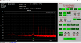
Here's my GB150D THD spectrum measurements at 1kHz, 8 ohms load.
There's an interface in between GB150D and QA400 so the output signal is always reduced to around 500mVrms.
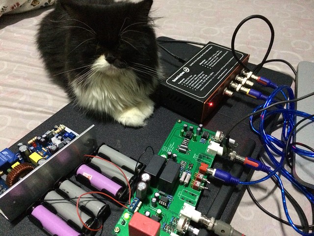
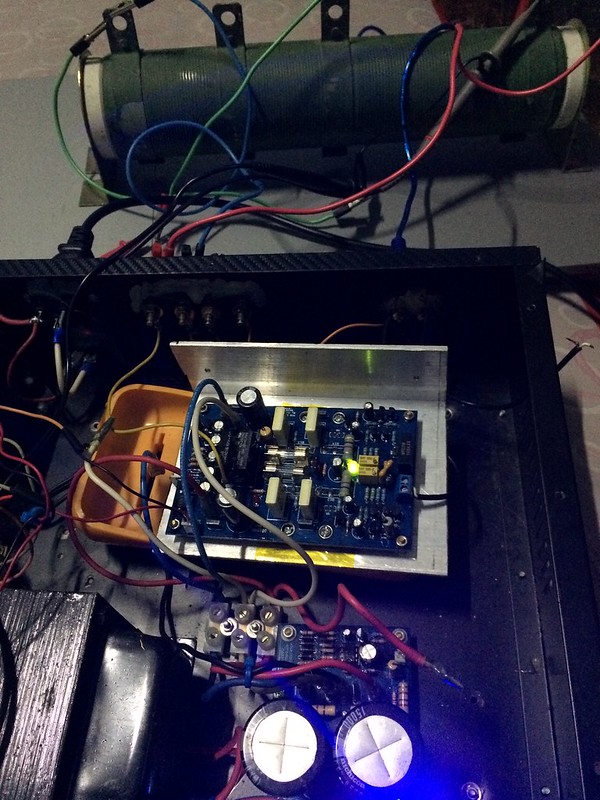
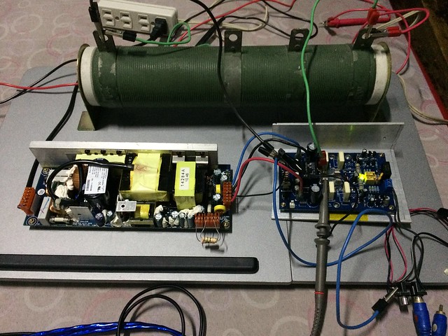
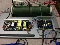
Setup pics (There's a cat nearby, she might have had affected the measurements 🙂)
QA400 and the interface for protecting QA400 from large output signals.
Rail Voltage +/-53V DC, bias current 25mA, cold start. Input is a balanced signal from THAT1646.
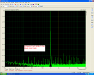
The Noise floor when the amplifier is unplugged.
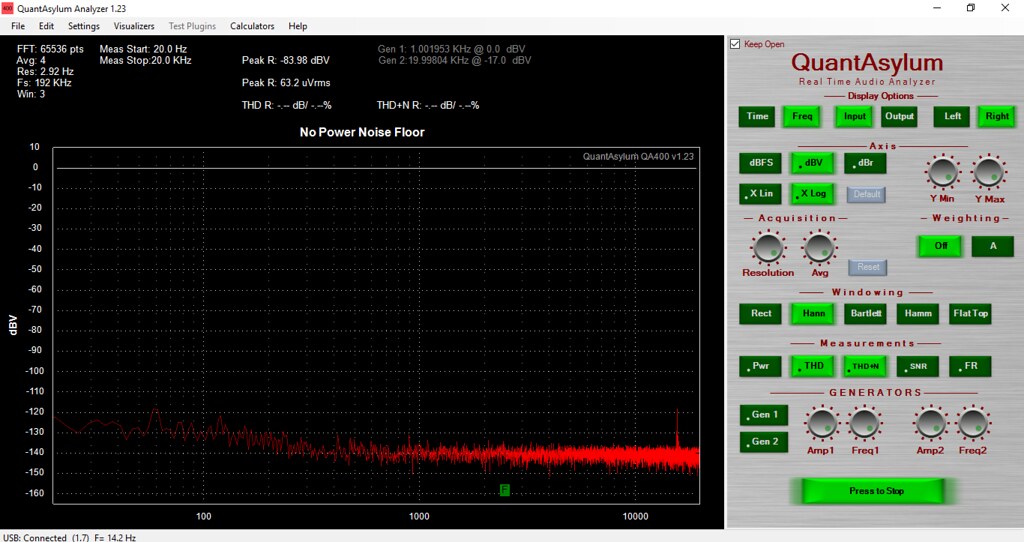
I can't remove the interference, once the amp is plugged, mains harmonics are there, I tried different wiring for ground... maybe next time I might be able to remove it.

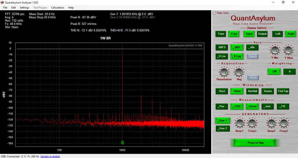
1W 8R
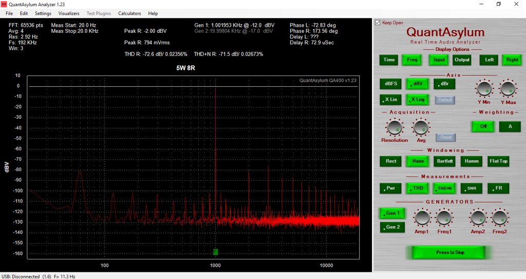
5W 8R (unbalanced, direct from QA400)
5W 8R (balanced, from THAT1646)

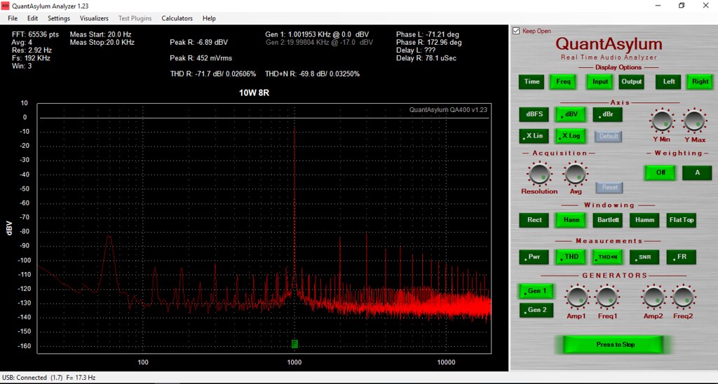
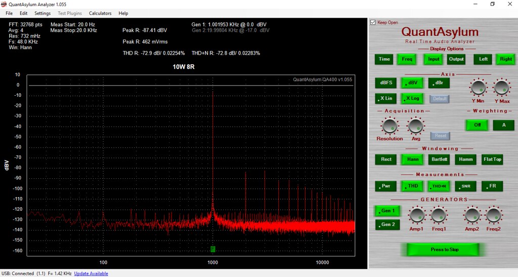
10W 8R
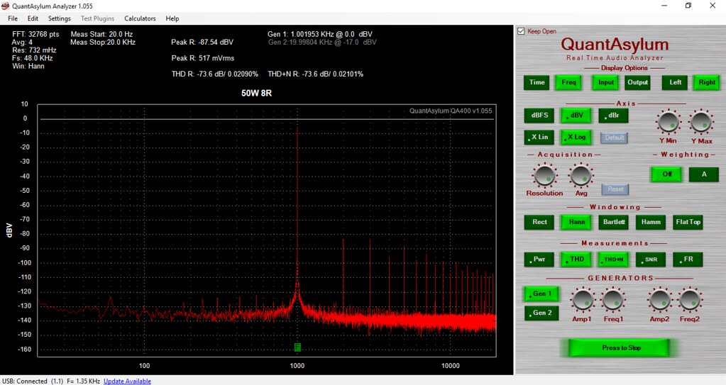
50W 8R

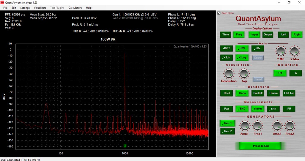
100W 8R
There's an interface in between GB150D and QA400 so the output signal is always reduced to around 500mVrms.
Setup pics (There's a cat nearby, she might have had affected the measurements 🙂)
QA400 and the interface for protecting QA400 from large output signals.
Rail Voltage +/-53V DC, bias current 25mA, cold start. Input is a balanced signal from THAT1646.
The Noise floor when the amplifier is unplugged.
I can't remove the interference, once the amp is plugged, mains harmonics are there, I tried different wiring for ground... maybe next time I might be able to remove it.
1W 8R
5W 8R (unbalanced, direct from QA400)
5W 8R (balanced, from THAT1646)
10W 8R
50W 8R
100W 8R
D
Deleted member 148505
Hi thimios, is that GB150D or SYMASYM?
I was able to remove mains interference when I measured my class-d module with qa400 + interface,
but I used SMPS as power supply of the amp, maybe I'll repeat my measurements using SMPS.
I was able to remove mains interference when I measured my class-d module with qa400 + interface,
but I used SMPS as power supply of the amp, maybe I'll repeat my measurements using SMPS.
No,it isn't GB150,it is the Symasui,an Ostripper design from Slewmaster thread.Hi thimios, is that GB150D or SYMASYM?
I was able to remove mains interference when I measured my class-d module with qa400 + interface,
but I used SMPS as power supply of the amp, maybe I'll repeat my measurements using SMPS.
I just post here to see how mains interference issue was solved.😉
D
Deleted member 148505
Ok this time I'm using an SMPS as power supply, the mains harmonics cleared up but the THD distortion percentage didn't change much, maybe the software does not include mains harmonics in the calculation.
As you can notice, the noise floor is higher on 1W and 5W, it is because divided by 10 attenuator on my interface is not activated. Maximum input for THAT1206 is around 8Vrms before the signal goes crazy. So for 10W measurements, I am enabling the div 10 switch.
THAT1206 has 6dB of attenuation, so the interface has a total of 26dB attenuation. (Original signal divided by 20).
To fine tune the signal going to QA400, the output of THAT1206 balanced receiver goes through baxandall attenuator, so I can set the voltage going to QA400 to -6dBV (around 500mVrms)
The setup
1W 8R load
5W 8R load
10W 8R load
50W 8R load
100W 8R load
Attachments


Here's my GB150D THD
Setup pics (There's a cat nearby, she might have had affected the measurements 🙂)
QA400 and the interface for protecting QA400 from large output signals.
Lovely. I really want it.
Can I have that cat ? You can keep the amp !🙂
@jlester87
Thanks for the details. The best numbers I've seen with a Jim's Audio GB150 was 65ppm IMD @1W and 160ppm IMD @150W with a nicely ordered linear supply and low bias. Can you best this with an SMPS?
Thanks for the details. The best numbers I've seen with a Jim's Audio GB150 was 65ppm IMD @1W and 160ppm IMD @150W with a nicely ordered linear supply and low bias. Can you best this with an SMPS?
D
Deleted member 148505
Lovely. I really want it.
Can I have that cat ? You can keep the amp !🙂
noo! 🙂🙂🙂
@jlester87
Thanks for the details. The best numbers I've seen with a Jim's Audio GB150 was 65ppm IMD @1W and 160ppm IMD @150W with a nicely ordered linear supply and low bias. Can you best this with an SMPS?
Can you point me to that post so that I can replicate the setup, method, tones that were used.. etc. thanks!
Can you point me to that post so that I can replicate the setup, method, tones that were used..
I generally let them out at night. Cats are very good at replicating, I find........😀
Hugh
@jlester87
The post I referred to wasn't on this site and my link is dead now. It was the typical IMD 19+20kHz test IIRC. The distortion was mostly 2nd and 3rd harmonic in character with a slight elevation in the 5th order at 150W. The speed of the supply would seem to help this amp so an SMPS should outperform a linear supply if you can avoid the RF and switching noise.
The post I referred to wasn't on this site and my link is dead now. It was the typical IMD 19+20kHz test IIRC. The distortion was mostly 2nd and 3rd harmonic in character with a slight elevation in the 5th order at 150W. The speed of the supply would seem to help this amp so an SMPS should outperform a linear supply if you can avoid the RF and switching noise.
Last edited:
D
Deleted member 148505
I generally let them out at night. Cats are very good at replicating, I find........😀
Hugh
Haha, good thing no one is stealing your cat.
- Home
- Amplifiers
- Solid State
- SKA GB150D now public domain...