1 The regulator is a single one but the can be built as positive or negative (one pcb for both types).
2 DC in yes but the quality doesn't have to be too good.
3 All parts are common parts. Even the voltage reference can be of 4 different types, just for the flexiblity
4 You can buy as many Gainclone pcb's you want") The performance is good and/or you can choose the parts you like as long as they fits in order to get the performance you want. My design uses mainly common parts. That was my design idea.
The performance is good and/or you can choose the parts you like as long as they fits in order to get the performance you want. My design uses mainly common parts. That was my design idea.
I suggest that you download the schematics and the partslists for these designs so you can see for yourslef which parts are used and all options.
2 DC in yes but the quality doesn't have to be too good.
3 All parts are common parts. Even the voltage reference can be of 4 different types, just for the flexiblity
4 You can buy as many Gainclone pcb's you want
The performance is good and/or you can choose the parts you like as long as they fits in order to get the performance you want. My design uses mainly common parts. That was my design idea.I suggest that you download the schematics and the partslists for these designs so you can see for yourslef which parts are used and all options.
Hi,
Managed to find the parts list didnt see that before!
Am i correct in saying that the IC's are the expensive parts ?
if so this is what i have found ...
IC1 LM317AEMP Positive voltage regulator, adjustable, 1A, 40 V, SMD Positive regulator 0.7
IC2 LM337IMP Negative voltage regulator, adjustable, 1A, 35 V, SMD Negative regulator 1
IC3 TL431AID Shunt regulator, 2,5-36V, 700mW, SO08, SMD Positive regulator 0.42
IC4 LM385Z Shunt regulator, 2,5-36V, 770mW, TO-92 Positive regulator 0.65
IC5 LM431ACM Shunt regulator, 2,5-36V, 280mW, SOT-23 Positive regulator 0.7
IC6 AD797AR Ultralow noise audio opamp SMD 7.47
IC7 LM385Z Shunt regulator, 2,5-36V, 770mW, TO-92 Negative regulator 0.65
IC8 TL431AID Shunt regulator, 2,5-36V, 700mW, SO08, SMD Negative regulator 0.42
IC9 LM431ACM Shunt regulator, 2,5-36V, 280mW, SOT-23 Negative regulator 0.7
Thats about £13 , does that sound correct.
Any more expensive parts to look at ?
Thanks again!
 £7.50 for an opamp and it wont even be used in the audio signal!
But i guess its one of the key elements.
Managed to find the parts list didnt see that before!
Am i correct in saying that the IC's are the expensive parts ?
if so this is what i have found ...
IC1 LM317AEMP Positive voltage regulator, adjustable, 1A, 40 V, SMD Positive regulator 0.7
IC2 LM337IMP Negative voltage regulator, adjustable, 1A, 35 V, SMD Negative regulator 1
IC3 TL431AID Shunt regulator, 2,5-36V, 700mW, SO08, SMD Positive regulator 0.42
IC4 LM385Z Shunt regulator, 2,5-36V, 770mW, TO-92 Positive regulator 0.65
IC5 LM431ACM Shunt regulator, 2,5-36V, 280mW, SOT-23 Positive regulator 0.7
IC6 AD797AR Ultralow noise audio opamp SMD 7.47
IC7 LM385Z Shunt regulator, 2,5-36V, 770mW, TO-92 Negative regulator 0.65
IC8 TL431AID Shunt regulator, 2,5-36V, 700mW, SO08, SMD Negative regulator 0.42
IC9 LM431ACM Shunt regulator, 2,5-36V, 280mW, SOT-23 Negative regulator 0.7
Thats about £13 , does that sound correct.
Any more expensive parts to look at ?
Thanks again!
£7.50 for an opamp and it wont even be used in the audio signal! But i guess its one of the key elements.
You reply fast mr PA! 
If a lower opamp is used then wouldn't that mean the circuit is overkill for the quality of output, or still using quite a good op amp (opa etc?) would produce excellent result, just not "Super".
The price of the op amp is pretty ok anyway - if its the only thing costing that much - I really just wanted to check that i had priced up the most expensive components about right and wasnt in for any nasty suprises!
Anyone in UK care to comment on component sources and prices ?
Thanks again Per,
Brian

Sold.
I'll put an order in for four then.
If anyone wants to offer to sell me some parts,
(because is seems for some you need to buy lots of them) I'll be quite happy to pay the total + a reasonable amount for their help. Other than that i'll have fun trying to get them myself!
Im suprised that more people dont ask you to get the common parts Per, seems to make sense to me!
I'll try and do some pay pal later tonight PA, thanks,
Brian.
There must over 100 units if you want to have a good price. Buying 19 opamps will not get you a very attractive price.brianuk said:Im suprised that more people dont ask you to get the common parts Per, seems to make sense to me!
Because this pcb is SMD it's also a bit more exclusive (meaning not common) than a regular holemounted one. Therefore is the interest rather low, but then again, I think SMD is cool and those other people who thinks the same can join me in this deal.
Hello,
Is there any point in using these for discrete circuitry (such as pre-amps) which have resistors (some high in value) connected to the supply rails and some resistors with variable currents being drawn through them. To me this seems to negate the advantage of very low Zout. The PSRR is still obviously better.
Was thinking that certain nodes wouldn't benefit.
Do you need ultra low impedance for supplying CCS for example, wouldn't a high impedance be OK ?
In otherwords, are they only really suitable for driving op amps ?
(transistors to transistors)
Interested in any answers
Yes good question Kevin.
I'd be using two with my active xover which has 7 opamps on it powered at +/-15v.
I presume these are powered direct, i think they just have the small caps for bypass.
So are these ideal for my application? Dont want to waste my time(and money).
(The other two i'd save for a dac)
I understand what you mean Per about the parts, like i said if you (or someone suitable- ideally you!) wants to order a few extra of the critical parts then i'd be grateful to add the parts cost + of course a finders fee if you see what i meant.
Thanks,
Brian
I'd be using two with my active xover which has 7 opamps on it powered at +/-15v.
I presume these are powered direct, i think they just have the small caps for bypass.
So are these ideal for my application? Dont want to waste my time(and money).
(The other two i'd save for a dac)
I understand what you mean Per about the parts, like i said if you (or someone suitable- ideally you!) wants to order a few extra of the critical parts then i'd be grateful to add the parts cost + of course a finders fee
if you see what i meant.Thanks,
Brian
When you think about it, many circuits presumes supply voltage with zero impedance. I have never used a super regulator in practical use so I don't know how much good it will do. I'll expect that you experience the same difference as when you change from TL071 to AD8610. You will get a lift in the sound quality which is hard to imagine before you have experienced it.Kevinbd said:In otherwords, are they only really suitable for driving op amps ?
(transistors to transistors)
I suspect that MC, MM and mic amps with discrete technology will benefit the most of a super regulator but I could be wrong here.brianuk said:So are these ideal for my application? Dont want to waste my time(and money).
The truth, the hole truth. and nothing but......
"Because this PCB is SMD it's also a bit more exclusive (meaning not common) than a regular hole mounted one."
I believe SMT is more common than through hole at this point. Since a PCB with through hole parts (and addition to the vias between layers) requires more holes to be drilled it should be more expensive. There is the addition time to drill more holes and tooling set up for several drill sizes. I have never turned a PCB whose cost was not based partly on the number of holes. If your board vendor is charging you more for SMT, I would be looking for another board vendor. There are ways of reducing board cost that are pretty easy if planned in the design phase.
1. Reduce PCB dimensions through less stuffing options or mount parts on both side of the PCB. Often through hole parts are mounted on one side and SMT on the other. This allows parts to be mounted where the body outline of the through hole part would prohibit mount on the through hole component side. For example think how little of the space under a radial eletrolytic cap is required for the pads for the electiclal connection and is wasted space on that layer but available on the other side of the PCB. On a one layer board you can mount the caps ( as well as other through hole parts on the no trace side and still mount SMT parts on the trace side.
2. Non plate trough holes. This requires soldering a wire through the vias and soldering both sides of a component lead if it makes electrical contract to a trace on both sides. With mostly SMT parts and a simple circuit this isn't that big a deal.
3. Single sided board, no plate through holes. Single sided boards are also easier to change parts on since you are not trying to get solder out of the plated through hole to remove a part.
4. Elimination of solder mask and silk screen. If your have a good component drawing and a relatively simple circuit the silk screen is really an unnecessary cost. Often on tight layouts the reference designator is covered by the part after it is installed, or reference designators are close enough together that it can be confusing which part goes with which designator. There are those who say that a solder mask degrades the sound. Non solder mask board require some type of plating for solderability and protection of the copper traces from oxidation. Electroless tin is supposed to sound better than reflowing the board with solder. A wave solder machine used to flow the solder plate on the PCB holds over a hundred pounds of solder. Rather than having to change it out, flux is added and the impurities are skimmed off the surface, the solder does wind up with quite a few impurities in it. I have seen gold plating used in audio products to get a nonoxidizing finish without using a solder mask. Gold plating has it's issues with solderability and nickel plating being used between the copper and gold.
Fred, I meant that SMD and DIY is not very common.
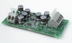
You are right about your comments about my pcb's are "professional" as I called and I won't do any single side boards. My minimum standard is what you see in my pictures. I won't settle for less.
Fred, I'm also puzzled by your comments because you are talking about when you are going to make 1000000 pcb's or so, so where do your comments fit in here?
- Status
- This old topic is closed. If you want to reopen this topic, contact a moderator using the "Report Post" button.
- Home
- Group Buys
- Sjöström Super Regulator group buy