"about 25 bucks"
25 bucks or 30 bucks... who cares... on the order of two pieces.
But if I had to take 200 pieces then I would think. 🙂
R3 is 100R or 1M
R8 is 0R (just bridge it?) or 27R
is it related to what transformers we use?
admit didn´t even start to search : )
R8 is 0R (just bridge it?) or 27R
is it related to what transformers we use?
admit didn´t even start to search : )
Put 100R and 0R....you don't need more sugar,which you get with optional Borbely WCF
Can you wait till tonight,to get more instructions?
I can't do that ,typing on phone
Can you wait till tonight,to get more instructions?
I can't do that ,typing on phone
arrr, manythanx for answers, stop typing on phone : ) didn´t know that.. thought of you sitting next to coffeepot and desktop : )
may I be excused for tonight ?
I'm so tired ..... not wanting to make some crucial mistake in parts nomenclature , so better not typing while almost sleeping ........
see ya tomorrow
zzzzzzzzzzzzzzzzzzzzzzzzzzzz(M going to zzzzzzzzzzzzzzzz)
🙂
I'm so tired ..... not wanting to make some crucial mistake in parts nomenclature , so better not typing while almost sleeping ........
see ya tomorrow
zzzzzzzzzzzzzzzzzzzzzzzzzzzz(M going to zzzzzzzzzzzzzzzz)
🙂
I'm still waiting for the invoice.
It will arrive comfortably for the new year at this speed.
I finally ordered.
Please allow us a short period of time to manufacture them.
Attachments

damned, too fast, wanted to stretch it over several evenings
@ZM:
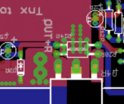
–you were too lazy to put proper values for R9-R12 (2x12k, 2x8k2) into package and instead a bunch of 10k 😀?
mhm, others..yes,
– should we bridge the left out Diodes D1, D2 ?
same, should we bridge the leftout R13, C3 (if not using the Edcors)?
–footprints of 100R Pots is for giggling 😀
made me jaleous, looking at your SMD solder job
–do you plan to do little hook up write up? things like "close jumper AFTER adjusting offset", and (important for me) a foolproof advise how the potis have to be set before powering up.
all best
st.
@ZM:
–you were too lazy to put proper values for R9-R12 (2x12k, 2x8k2) into package and instead a bunch of 10k 😀?
mhm, others..yes,
– should we bridge the left out Diodes D1, D2 ?
same, should we bridge the leftout R13, C3 (if not using the Edcors)?
–footprints of 100R Pots is for giggling 😀
made me jaleous, looking at your SMD solder job
–do you plan to do little hook up write up? things like "close jumper AFTER adjusting offset", and (important for me) a foolproof advise how the potis have to be set before powering up.
all best
st.
@ZM,
hope I remember right .... was something with footprint on the board for the diodes (showing wrong direction)?
hope I remember right .... was something with footprint on the board for the diodes (showing wrong direction)?
on that Diode there ist "Note!" remark printed on PCB. I first wondered, cause on schematic it is mentioned also, mostly done when correction on PCB print was too late.
I´m not shure, but guess it is right way (like printed on PCB) for M25, other way for Sissy Sit,
best
I´m not shure, but guess it is right way (like printed on PCB) for M25, other way for Sissy Sit,
best
We all have questions galore, but Mighty ZM promised us detailed build thread with pictures, so i suggest we all wait (so hard, i know) patiently and the reward shall be the mother of all build threads. And it will be way more economical for ZM's time to have all(most?) questions answered in a single place.
Of course, that is easy for me to say, i don't yet have all the parts needed for even a test-bench build, and i try real hard to be patient.
Of course, that is easy for me to say, i don't yet have all the parts needed for even a test-bench build, and i try real hard to be patient.
Have just tested the three THF51-S ordered from pras1170. I agreed with his measurements. They were all virtually identical at -2.87V for 2A so I am very happy.
I noted the shipping label was marked FROM - Handsome!
Thanks for a good transaction pras1170 .
I noted the shipping label was marked FROM - Handsome!
Thanks for a good transaction pras1170 .
- Home
- Amplifiers
- Pass Labs
- SissySIT