I need to prepare materials
I need to prepare materials: ammeter, voltmeter, fan resistance, adjustable resistance, 9V battery, 24V power supply
I need to weld well to make a test machine, right?
I will try to prepare the materials and upload the pictures
for THF51-S , body is drain ( no need for isolation for test , just keep heatsink electrically from other voltage potentials , other than + rail), fat protruding pin is source,while thin protruding pin is gate
again , any power N channel JFet , having ebough cojones , and having gate voltage in range of -1 to -3V6 is adequate for SissySIT circuit
if you sort your P channel mosfets , and use those with highish gate voltage (for -19 to -25V and Iq 1A8 to 2A) , in area of -4V5 , JFet can have even -4V gate voltage for intended conditions
have more questions , shoot
I need to prepare materials: ammeter, voltmeter, fan resistance, adjustable resistance, 9V battery, 24V power supply
I need to weld well to make a test machine, right?
I will try to prepare the materials and upload the pictures
I am off the grid (absent from web entirely) from tomorrow morning to Friday
if you need help , somebody will chime in
if you need help , somebody will chime in
I am off the grid (absent from web entirely) from tomorrow morning to Friday
if you need help , somebody will chime in
good
Thank you for your
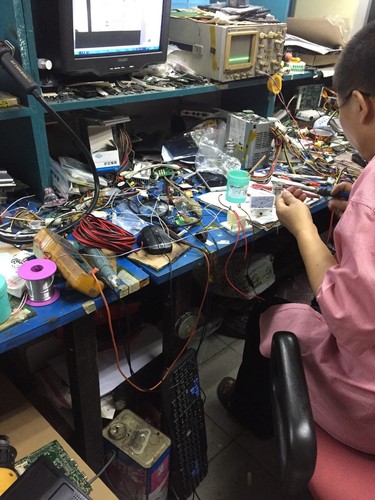
Here is my test rig in action.
I used a wall wart power supply in place of the 9V battery. It actually outputted 12VDC even though it was rated at 9VDC. However, since the 10K pot limits the voltage to the THF-51S, the higher voltage was not a problem. I did not have a power supply of 19 to 25V so I borrowed the power supply from one of my projects. I temporarily disconnected the power supply and took the power off it. However, the supply voltage was much higher than 25VDC so I plugged the supply into a variac and reduced the input AC to the point that the supply outputted 24VDC.
For connections, I used clip leads for everything except for the resistor in the bias supply. I soldered that to the 10kohm pot. For the 1kohm resistor, I soldered two 600 ohm resistors in series to the pot. I figured 1.2kohm was close enough. One thing to keep in mind is that with the use of clip leads, care must be taken to not jar any connections loose while the test setup up is powered up. You do not want to lose the bias voltage while the main voltage is applied.
The THF-51S was attached to a heat-sink, with silicone heat-sink compound in between the sink and THF-51S. The aluminum heat sink that I used was 325mm x 120mm and weighed 1.3kg. After five minutes, the THF-51S was hot but I could still keep my finger on it. As Zen Mod stated, the THF-51S should be heat-sinked. A fan alone is probably not adequate cooling. With my heat-sink, it was big enough that I did not need a fan.
I tested the THF-51S at 24V and 1.8A. As can be seen in the photo, I used three meters. One inline for current and one each for Vgs and Vds.
Attachments
Has anyone considered trying to run two SissySIT channels off of a single transformer? With an autoformer we could parallel channels in-phase, but we'd have to use it as a traditional interstage transformer if we'd want to phase-split and feed two channels in opposite phase, or am i missing something?
THF-51S tested
I received my THF-51Ss from watanabetomoaki last week. I purchased four and they arrived nine days after I purchased them so that was good.
They were grouped in twos with numbers handwritten on the bottom. One group had 2.5 written on both and the other group had 2.2 on one and 2.4 on the other.
I tested them at 24V and !.8A as shown in the post #264 above. The results were as follows:
2.2............-3.11V
2.4............-3.19V
2.5............-4.46V
2.5............-3.54V
Three of the THF-51Ss are quite usable for the SissySit, although the -3.54V is getting close to the limit. The -4.46V is much too high.
I don't know the meaning of the handwritten numbers on the bottom of the devices. I sent watanabetomoaki a message four days ago asking the question but I have not heard back from him yet.
Has anyone else tested their THF-51S from watanabetomoaki? Did yours have handwritten numbers on them, or do you know their significance?
I got 2 from watanabetomoaki, one marked 1.7 and the other marked 1.8 by him.
I tested them at 19V and 1.8A, both got -2.3V.
I tested them at 19V and 1.8A, both got -2.3V.
S G D
Hello, I have made the experiment
However, it is troublesome for me to send the picture to you in BBS. I sent it to you by email, but the display was not successful. It may be that your email has the setting of not accepting the email from strangers
All the emails I sent to others were successful and sent to you were unsuccessful
Now, S G D, I want to make sure the position of the foot
Left foot 1. Grid
2. Source
Base plate 3. Drain.
I am off the grid (absent from web entirely) from tomorrow morning to Friday
if you need help , somebody will chime in
Hello, I have made the experiment
However, it is troublesome for me to send the picture to you in BBS. I sent it to you by email, but the display was not successful. It may be that your email has the setting of not accepting the email from strangers
All the emails I sent to others were successful and sent to you were unsuccessful
Now, S G D, I want to make sure the position of the foot
Left foot 1. Grid
2. Source
Base plate 3. Drain.
Now, S G D, I want to make sure the position of the foot
Left foot 1. Grid
2. Source
Base plate 3. Drain.
Which one can answer me, I think it is like this
Are you the same idea?
Left foot 1. Grid
2. Source
Base plate 3. Drain.
Which one can answer me, I think it is like this
Are you the same idea?
I got 2 from watanabetomoaki, one marked 1.7 and the other marked 1.8 by him.
I tested them at 19V and 1.8A, both got -2.3V.
Which one can answer me, I think it is like this
Are you the same idea?
Now, S G D, I want to make sure the position of the foot
Left foot 1. Grid
2. Source
3. Drain pole
For THF51-S , body is drain ( no need for isolation for test , just keep heatsink electrically from other voltage potentials , other than + rail), fat protruding pin is source,while thin protruding pin is gate.
Please see Post#81.
Please see Post#81.
I got 2 from watanabetomoaki, one marked 1.7 and the other marked 1.8 by him.
I tested them at 19V and 1.8A, both got -2.3V.
It does look like the numbers indicate some sort of matching. However the large discrepancy between the two that I have that are marked 2.5 seems out of place.
Watanabetomoaki has replied with an answer:
"The written numbers on them means Id (A), at Vds=25V Vgs=-1V aroun 25 degreeC."
"The written numbers on them means Id (A), at Vds=25V Vgs=-1V aroun 25 degreeC."
Went ahead and ordered some Toroidy iron, a pair of 300VA Audio each having twin 0-18-21-24V @ 150VA each.
The premium was only around €20 or thereabouts, and this way i have some options in other Pass designs to try out later, and if not, still an infinitesimal waste compared to past ones...
I was given the choice on how to wind them, opting for not being able to use all the secondaries in series, to make a 0-60V, instead opting for bifilar wound, that's the only choice i'm not sure of.
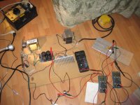
This is the material I prepared (the experiment has not officially started yet, because the voltmeter has a problem, it stays there all the time and does not return to zero. I will buy another voltmeter tomorrow to replace it) : according to # 81
Everybody take a look at it for me, right?
I have not turned on the power, everything is imitation state, has not officially plugged in power
Let's take a look. Is that right?
5 a current meter
9 v battery
10 v voltage meter
1 w 1 k resistor
10 k locator
24 v power supply
24V dc fan


Everybody take a look at it for me, right?
I have not turned on the power, everything is imitation state, has not officially plugged in power
Let's take a look. Is that right?
5 a current meter
9 v battery
10 v voltage meter
1 w 1 k resistor
10 k locator
24 v power supply
24V dc fan
For THF51-S , body is drain ( no need for isolation for test , just keep heatsink electrically from other voltage potentials , other than + rail), fat protruding pin is source,while thin protruding pin is gate.
Please see Post#81.
This is the material I prepared (the experiment has not officially started yet, because the voltmeter has a problem, it stays there all the time and does not return to zero. I will buy another voltmeter tomorrow to replace it) : according to # 81
Everybody take a look at it for me, right?
I have not turned on the power, everything is imitation state, has not officially plugged in power
Let's take a look. Is that right?
5 a current meter
9 v battery
10 v voltage meter
1 w 1 k resistor
10 k locator
24 v power supply
24V dc fan
i have mesured my pair of TH51s and at 18V VDS i have one at 850ma for -1.92V gate bias and the other at 950ma
is it ok for the project ? 😕
is it ok for the project ? 😕
Let's take a look. Is that right?
I think that you need to mount THF-51S on some heatsink...
Last edited:
Small feet = G
Big foot = S
Substrate=D
Everyone said: Right?
Yes all is OK 🙂
- Home
- Amplifiers
- Pass Labs
- SissySIT