22v5dc, resulting from usual arrangement with 18Vac Donuts, is really sweet spot
so, 22Vdc to 25Vdc rails, is what you need to think of
which means - if they already have 25Vdc bipolar, go for it
so, 22Vdc to 25Vdc rails, is what you need to think of
which means - if they already have 25Vdc bipolar, go for it
I'm building with a conventional CRC power supply but did wonder about using SMPSs so will be interested in how this works out.
I considered ordering a couple of these, customised for the correct SissySIT voltages.
SMPS500R +-45V 230V 500W Switch Mode Power Supply | Hifime Audio
I have used these SMPS PSUs in a couple of Class-D projected and they were very good- completely silent on the audio out and very good quality. I bought them from eBay : SMPS500R +-54V (dual voltage) 230V SMPS Power Supply, PCBStuff, Connexelectronic | eBay
Obviously would need the correct Vout for your SIT requirements (what are they?) plus has auxiliary output for powering speaker protection circuits or other items.
-Jon
well, that is in the end going to be extremelly Fugly!
while I sent abroad more than 2/3 of all recent amp kits, I'm just about ready to receive bunch of LT3092, so I can complete shipment, and invest some time in next batch of new amps


Goody. Almost winter-eve. Brain told me this morning, "If you build Iron turtle and XA252, you wont need to build anymore." Really? silly brain, trix are for kids. I mean really...it was giggling, in background about "once that's done we'll ding dong him until he builds balanced version too." Evil, I tell you.
Russellc
Last edited:


SissySIT progress..
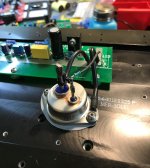
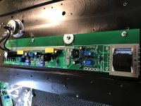
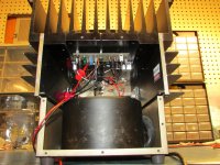
Taking a short break and thought I might show some progress. Out with the F4 and on to the SS R.3. About to start final wiring on this first channel. Then to power up and hope that careful, slow, patient assembly has paid off.
Taking a short break and thought I might show some progress. Out with the F4 and on to the SS R.3. About to start final wiring on this first channel. Then to power up and hope that careful, slow, patient assembly has paid off.
Attachments
I've been looking to build a switched volume attenuator for my SissySIT build but I was just rummaging through my spare parts and came across an Academy Audio Muses volume control module I had forgotten about - seems like a good candidate to go in front of my SissySIT and with the input buffer being JFET based I shouldn't require a coupling cap.
Last edited:
I am looking at using 2 Heatsink USA 8”X3” serrated fin heat sinks per Channel and trying to figure how tall to go. The spec from Heatsink is .66 C/W/3” , ZM says the heat output is about 80 Watts per channel, My ambient max will be 26c. Not sure of formula for calculating how many watts .66 C/W/3” dissipates and how to scale that up to Heatsink height . My ideal would be 2-6” tall per side.
Link to Heatsink- 8.000" Wide SERRATED FIN Extruded Aluminum Heatsink - HeatsinkUSA
Thanks
Bill
Link to Heatsink- 8.000" Wide SERRATED FIN Extruded Aluminum Heatsink - HeatsinkUSA
Thanks
Bill
Not sure of formula for calculating how many watts .66 C/W/3” dissipates and how to scale that up to Heatsink height . My ideal would be 2-6” tall per side.
80Watts x 0.66 = temperature rise of 52.8°C so if your ambient temp is 26°C the 3inch tall heatsinks will get to 78.8°C (in a perfect world!) - I suggest the three inch heatsinks are too small. The 6inch heatsinks will not achieve double the performance of the 3inch ones but might be OK if you're OK with a temperature around 60°C - personally I would go bigger.
I am looking at using 2 Heatsink USA 8”X3” serrated fin heat sinks per Channel and trying to figure how tall to go. The spec from Heatsink is .66 C/W/3” , ZM says the heat output is about 80 Watts per channel, My ambient max will be 26c. Not sure of formula for calculating how many watts .66 C/W/3” dissipates and how to scale that up to Heatsink height . My ideal would be 2-6” tall per side.
Link to Heatsink- 8.000" Wide SERRATED FIN Extruded Aluminum Heatsink - HeatsinkUSA
Thanks
Bill
two of these per side , so ending in sink 3" tall and 16" deep should get you in ballpark
Babysitter in Summer and that's it
of course - if you still didn't bought them - pony up for 4" tall
I appear to have two properly functioning channels now. The delayed OS bias start up time caught me off guard a bit, but I was patient all seems well. I guess the filaments had to warm up first.. Haven't had a chance to get a proper impression yet. I've only run one channel at a time for setup and testing so far. I need to throw together some interconnects for the pair (monoblocks). If this amp sounds good I'm sure it's because of the Cardas Eutectic solder I used...😉
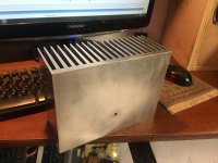
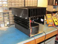
My chassis's are not sexy like most shown here. More suited for a locomotive which is where they came from. These chassis's were destined for the scrap heap where I'm employed. I've built 1.21 giga-amps in these... BA-1, F4, F5, F6, Aleph J, etc., etc. I did make some mesh front panels to make them slightly more presentable. Each weighs 45 lbs. Working in these is difficult. Like playing that old classic game called "Operation". Slip and get buzzed. Maybe I'll try to get a family picture of the Sissy brothers as it "SIT's" now 🙄. Pictures are one of my old veroboard / point to point wired BA-1's with Semisouth where it counts. SS R.3 dropped right in with that UMS designation, and only had to drill and tap a single hole to get the welding drek Tokin mounted.
Attachments
Thanks for the help, I will go with 6” then. I have decided to go with SMPS power supplies so this one will be a bit pricey. My plan is power supply in separate case and extra set of caps in amp case. I hope the SMPS will not struggle with the slow start up time and extra caps.
Bill
Bill
Last edited:
- Home
- Amplifiers
- Pass Labs
- SissySIT R.3