Simulation of the distortion.
Everything is below 0.0130% for 8 Ohm 1kHz.
Watt - THD
01 - 0.0011%
02 - 0.0034%
05 - 0.0088%
10 - 0.0101%
15 - 0.0106%
20 - 0.0113%
25 - 0.0123%
26 - 0.0127%
Everything is below 0.0130% for 8 Ohm 1kHz.
Watt - THD
01 - 0.0011%
02 - 0.0034%
05 - 0.0088%
10 - 0.0101%
15 - 0.0106%
20 - 0.0113%
25 - 0.0123%
26 - 0.0127%

Since hearing, ear distortions are included, i.e. are part of the hearing, ear system, it does not seem too necessary to take them into account.
And my experience is that overdamped speakers, even those with low distortion, sound unpleasant. The ear seems to love, to need distortions. Especially since we hear materials, we need balanced mixtures of materials. For wooden boxes with drivers inside, I recommend adding metals, whether as a base or as plugs, sockets or as a clamp and decoupling the speakers. Until it clicks sonically.
Experience has also been made in instrument making: whether pianos with wooden frames or steel frames, or organs: the same pipes/frequencies made of different materials, e.g. wood/tin, sound different. When organists draw registers, they not only draw different pipe lengths, but also different materials. This makes the organ sound varied: the ear hears material resonances. Also in loudspeakers and audio electronics.
Hi Lineup
In your sim try making C1 and C3 much higher in value and see how the 1kHz THD drops.I think it will surprise you 🙂
In your sim try making C1 and C3 much higher in value and see how the 1kHz THD drops.I think it will surprise you 🙂
Hi Lineup
I use a single rail-to-rail bypass at each opamp. 100nF ceramic. This keeps the noise currents out of ground. Self recommends this, too, but I see most designs with two caps frrom the rails to ground - it is traditional and maybe a bit lethargic?
The cap around the opamp should be as small as possible while providing stability .
Hi
There is a little point regarding decoupling that took me decades to realise.
For example, we typically see the front end of a power amp decoupled from the main supply using series resistors in the supply lines followed by filter caps to ground. The RC constant typically is not long enough to provide very good isolation at low frequencies, which can lead to oscillation if the layout is bad - it has to be quite terrible, actually, to cause a problem.
What really matters for the circuit is to have the filter cap right at the circuit it provides filtering for. This keeps the circulating current path tight and this current is unlikely to be interfered with by other currents, nor is it likely to interfere with other currents. The decoupling resistors can be dispensed with in many situations, particularly in circuits where there are many opamps.
Opamps have a high PSRR and only need local filtering to remain stable - same as voltage regulators, which are small amplifiers that have a simple job. The bulk local filters (usually electrolytic caps) should be as close to the opamp as is possible, and can in fact support a few opamps without much concern. The high-frequency bypass across the opamp supply pins should be soldered to the underside of the package using through-hole or as close as possible for SM. In the "field of opamps" circuits, the use of local filter caps distributed over the board enhances stability and reduces intermodulation distortions.
In a power amp front-end, we may want the front-end to have extremely clean or stable regulated voltages to maintain bias conditions and to reduce noise. here we may use discreet or IC regulators, or just active hum filters. passive approaches would require much higher-value filter caps than are generally used.
If you use IC regulators for audio circuits, it is imperative to have a massive output filter cap to squash the IC's frequency response. There should be a tight local cap and the rest can be distributed as appropriate.
I made similar one with BJT output 20 years ago. R15, R16 in #87 could be bootstrapped.
It should be possible to use opamps(like OPA1611, OPA627, LME49710)with +/-15V and then some voltage gain and then using between +/-35 and 45V rail supply. Then you use maximum potential of the parts. You get 80 a 100watt.
All for minimal distorsion.
All for minimal distorsion.
Hello after a break caused by personal matters
I had to suspend my DIY activity for a few months
I am slowly coming back and will continue the projects I started
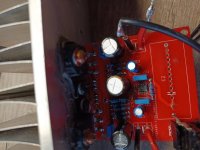
I launched 1 channel today
It was not without problems and a small BOOOM - one capacitor on the PCB has reverse polarity The board has not been cleaned yet ;-)
After correction it seems to be working properly Checked on a dummy load of 8 Ohm
Offset below 2mV
Power supply +/-23V
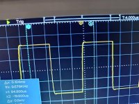
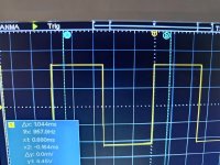
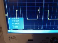
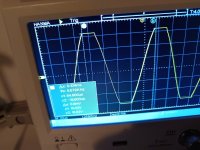
Sin and square waveforms are correct
As soon as I find the time I will launch the second channel and see what listening impressions
Distortion measurements in the future
I had to suspend my DIY activity for a few months
I am slowly coming back and will continue the projects I started
I launched 1 channel today
It was not without problems and a small BOOOM - one capacitor on the PCB has reverse polarity The board has not been cleaned yet ;-)
After correction it seems to be working properly Checked on a dummy load of 8 Ohm
Offset below 2mV
Power supply +/-23V
Sin and square waveforms are correct
As soon as I find the time I will launch the second channel and see what listening impressions
Distortion measurements in the future
Attachments

Looks like peaking in post 97 and is ringing in post 98 already at 10k
Was decoupling added? or was the simplified schematic built as is.
Is marginally stable. Anybody check stability.
Circuit could use bootstrap for current sources. Has been mentioned many times.
Have driven quite a few Diamonds with opamps in sim. usually need small series resistors on the power pins to stabilize.
Tina Ti seems to show this, not sure about other sims. I add internal resistance to the voltage sources so decoupling becomes needed
in sim to stabilize. Better not to test with " ideal" voltage sources.
@ZoltanChivay
Is doing some great work.
Unfortunately I have posted this circuit behind me.
But still I think it is very good.
Is doing some great work.
Unfortunately I have posted this circuit behind me.
But still I think it is very good.
- Home
- Amplifiers
- Solid State
- Sioux - 26 Watt OPA552 with Diamond Buffer output