Don't try this at home 🤣Don't try this circuit at home.
Made my day!

When you get old you just seem to know things. Jokes on the side, to balance they must track temperature. Common heatsink is even better they will track the environmental temp even closer and stabilise each other. Should not be on the main heat sink then they track the output pair thermals, not what you want, latency could lead to stranger things. Nice work my friend, I love your layouts, component's lining up like in a Russian military parade.Hi Nico
This is not the first amplifier in my life..... 😎
Drivers must be thermally coupled
I was also thinking of putting them on the heat sink with Laterals
Not quite true, they behave like variable resistors, not like a semi conductor.The lateral Mosfets have a negative temperature coefficient once they are conducting sufficient bias current. Thus no source resistors are needed.
Kindly check what happens if you place C6, 22pF across R4 instead. I am thinking in terms of feeding back from the overall output rather than the driver bases. However, if you find your solution adequate then don't worry. A phase margin of >60 degrees is more than most amplifiers I have ever seen. If the result of C6 paralleled with R4, then no PCB changes are required as the cap can be soldered directly across R4 without looking out of place and has no long (or any) tracks that include inductances.
If this is now final in your opinion, very well done and I hope the members appreciate your and Zoltan's efforts!
If this is now final in your opinion, very well done and I hope the members appreciate your and Zoltan's efforts!
Last edited:
Hello 🙂
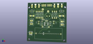
Now Sioux is ready to be built.
One thing to adjust in your setup:
R13 and R14 should set the bias in the output MOSFETs.
Chose those 2 resistors to get bias 200-300mA in the output.
300mA is to prefer.
Max output is like 26W into 8 Ohm.
Of course more into 4 or 6 Ohm.
Upper bandwidth is ~230kHz.
So there is no input filter necessary.
I did one for you!two thumbs up.
This time I decided it would be better to make a single board for each channel
It is simply much cheaper - I made a quick estimate in JLCPCB and 10 pieces cost 6 euros with shipping costs (I have a promotion)
A single large board - two channels + power supply is much more expensive
Is anyone interested in the boards? (Cost of 2 pieces 1.2 euros)
If so - you have to add additional shipping costs from France to you (I think about 5 euros - to be checked)
Attachments

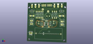
CorrectedIn,gnd printing error
Thanks for checking
Attachments
Nice compact layout ZC. I prefer the single channel without psu approach.👍🏻
I hate to be annoying but….
I don’t see smd pads for opamp bypass caps? Are they on the backside of the board?
Appreciate all your time spent on these amp layouts, Thanks!

I hate to be annoying but….
I don’t see smd pads for opamp bypass caps? Are they on the backside of the board?
Appreciate all your time spent on these amp layouts, Thanks!
I checked the OP-AMP datasheetI don’t see smd pads for opamp bypass caps?
This time there is no recommendation to use smd ceramic so for decoupling we have electrolyte + small foil capacitor
But if you really need it, let me know.
The OPA552 datasheet? It clearly shows 2 x 100nF and 1 x 10nF (all SMD) required in the recommended layout section (10.2). Ceramic caps are definitely assumed for such high frequency decoupling as the self-resonant frequency has to be high enough and wound caps would not be suitable (some film caps are multilayer and suitable, some are not, its easy just to specify MLCC ceramic which are cheaper anyway).I checked the OP-AMP datasheet
This time there is no recommendation to use smd ceramic so for decoupling we have electrolyte + small foil capacitor
- Home
- Amplifiers
- Solid State
- Sioux - 26 Watt OPA552 with Diamond Buffer output