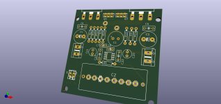
Layout examples:

Note the direct 10nF between V+ and V- is the key high-frequency component, not sure why only the DDPAK-7 example has the 100nF to-ground bypass caps shown. The datasheet mentions having a good ground-plane: "The circuit board must have as much ground plane area as possible" - though this is probably to do with heat-dissipation, not just stability.
Note the direct 10nF between V+ and V- is the key high-frequency component, not sure why only the DDPAK-7 example has the 100nF to-ground bypass caps shown. The datasheet mentions having a good ground-plane: "The circuit board must have as much ground plane area as possible" - though this is probably to do with heat-dissipation, not just stability.
Thanks for the info
I'm not a big fan of ground plane
I usually make separate traces for decoupling and signal and connect them to one common point
I haven't had any problems with oscillations so far
I'm not a big fan of ground plane
I usually make separate traces for decoupling and signal and connect them to one common point
I haven't had any problems with oscillations so far
Zoltan, R1 ident fall right on the SMD solderpad, kindly move it sideways. Also the extra input Cap, C2 through holes don't have pads, just leave the mask of the whole row, it seems gold plated so no worries about erosion.
Hi iineup,
As the text in the 8.1 paragraph notes, the OPA552 is decompensated and needs a gain of 5 (14dB) to be stable. With respect to the opamp as shown in your post 45 schematic, I think the shunt feedback from output (C6) makes good sense, but question if it would be stable with the OPA552. The combination of C6 and R5 form a -3dB corner at about 4.8MHz and the opamp gain will decrease further with rising frequency--- much less than the minimum stable gain of 14dB.
I can't explain why simulation would show good phase margin, but I wonder what would gain and phase would be if analyzed at the opamp output rather than at the output.
In any case, I believe the circuit could be made stable with the OPA551.
Last edited:
Gerber files are ready but first I want to build a prototype and check if everything workswhats the power supply for this? and is there a gerber file ready yet on this project?
I think I will order the boards next week
2x18VAC transformer, rectifiers and Capacitance.@lineup ignorant question ... sorry ... whats the power supply for this? and is there a gerber file ready yet on this project?
Simulation shows moderate distortion.Lineup how about distorsion and noise figures?
THD 0.0011%
Bandwidth 250kHz, so no need for input RC filter
GainMargin and PhaseMargin is okay thanks to the 22pF compensation
Noise can I not test - I leave that to others
Max 26.3 Watt
My simulation shows:View attachment 1356990
Hi iineup,
As the text in the 8.1 paragraph notes, the OPA552 is decompensated and needs a gain of 5 (14dB) to be stable. With respect to the opamp as shown in your post 45 schematic, I think the shunt feedback from output (C6) makes good sense, but question if it would be stable with the OPA552. The combination of C6 and R5 form a -3dB corner at about 4.8MHz and the opamp gain will decrease further with rising frequency--- much less than the minimum stable gain of 14dB.
I can't explain why simulation would show good phase margin, but I wonder what would gain and phase would be if analyzed at the opamp output rather than at the output.
In any case, I believe the circuit could be made stable with the OPA551.
GainMargin 54dB
PhaseMargin 67 Deg
with OPA552 and C6=22pF
Thanks for the data. My goal is to go for THD < 0.0000x %.
https://www.diyaudio.com/community/...-1-opamp-2-mosfet.416745/page-14#post-7804629
https://www.diyaudio.com/community/...-1-opamp-2-mosfet.416745/page-14#post-7804629
Last edited:
It is easy to say, but less easy to achieve, your speakers are >1% is there any point.
Speaker manufacturers/designers has progressed very slowly over the past 100 years. Maybe you should look into plasma speakers then an amplifier. Also hear about gas discharge speakers and fans with variable blades, I am not a mechanical wizard at all. I cannot think of anything that can go very very loud without any form of distortion, but you can have something that is very soft and have zero distortion.
EDIT: Has anybody anywhere measured the distortion introduced by one's ear/hearing mechanism. Where does it start falling appart?
EDIT: Has anybody anywhere measured the distortion introduced by one's ear/hearing mechanism. Where does it start falling appart?
Last edited:
- Home
- Amplifiers
- Solid State
- Sioux - 26 Watt OPA552 with Diamond Buffer output
